System and Peripheral Control Registers
www.ti.com
186
SPNU563A–March 2018
Submit Documentation Feedback
Copyright © 2018, Texas Instruments Incorporated
Architecture
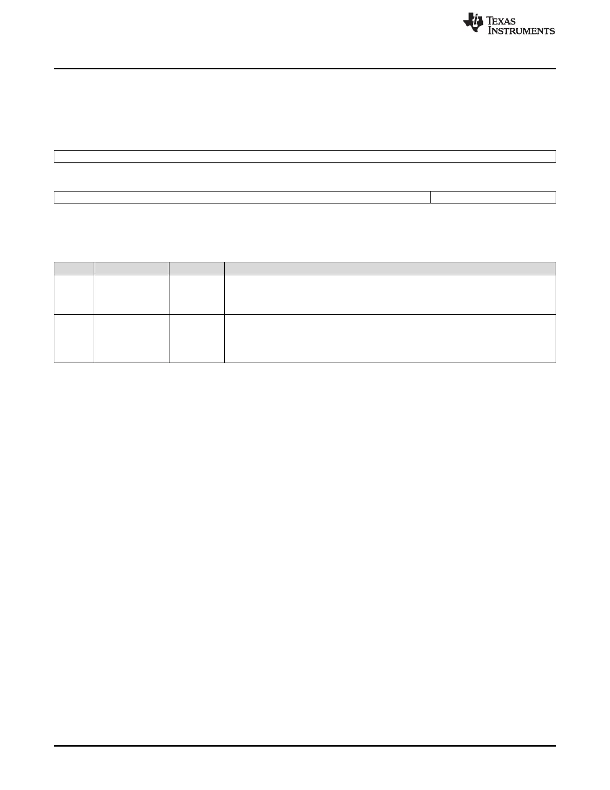
2.5.1.33 DFT Control Register 2 (DFTCTRLREG2)
This register is shown in Figure 2-40 and described in Table 2-52. For information on filtering the RFSLIP
see Section 2.5.2.7.
Figure 2-40. DFT Control Register 2 (DFTCTRLREG2) (offset = 94h)
31 16
IMPDF(27:12)
R/WP-0
15 4 3 0
IMPDF(11:0) TEST_MODE_KEY
R/WP-0 R/WP-5h
LEGEND: R/W = Read/Write; WP = Write in privileged mode only; -n = value after reset
Table 2-52. DFT Control Register 2 (DFTCTRLREG2) Field Descriptions
Bit Field Value Description
31-4 IMPDF[27:0] DFT Implementation defined bits.
0 IMPDF[27:0] is disabled.
1 IMPDF[27:0] is enabled.
3-0 TEST_MODE_KEY Test mode key. This register is for internal TI use only.
0-Fh
(except Ah)
Register key disable. All bits in this register will maintain their default value and cannot be
written.
Ah Register key enable. ALL the bits can be written to only when the key is enabled.

 Loading...


