0
1
S2
1
0
S1
RED
OutIn
Risingedge
delay
(10-bit
counter)
(10-bit
counter)
delay
Fallingedge
In Out
FED
1
0
S3
0
S0
1
EPWMxA
EPWMxB
DBCTL[POLSEL] DBCTL[OUT_MODE]
S5
DBCTL[IN_MODE]
1
0
S4
0
1
EPWMxA in
EPWMxBin
DBCTL[HALFCYCLE]
www.ti.com
ePWM Submodules
2029
SPNU563A–March 2018
Submit Documentation Feedback
Copyright © 2018, Texas Instruments Incorporated
Enhanced Pulse Width Modulator (ePWM) Module
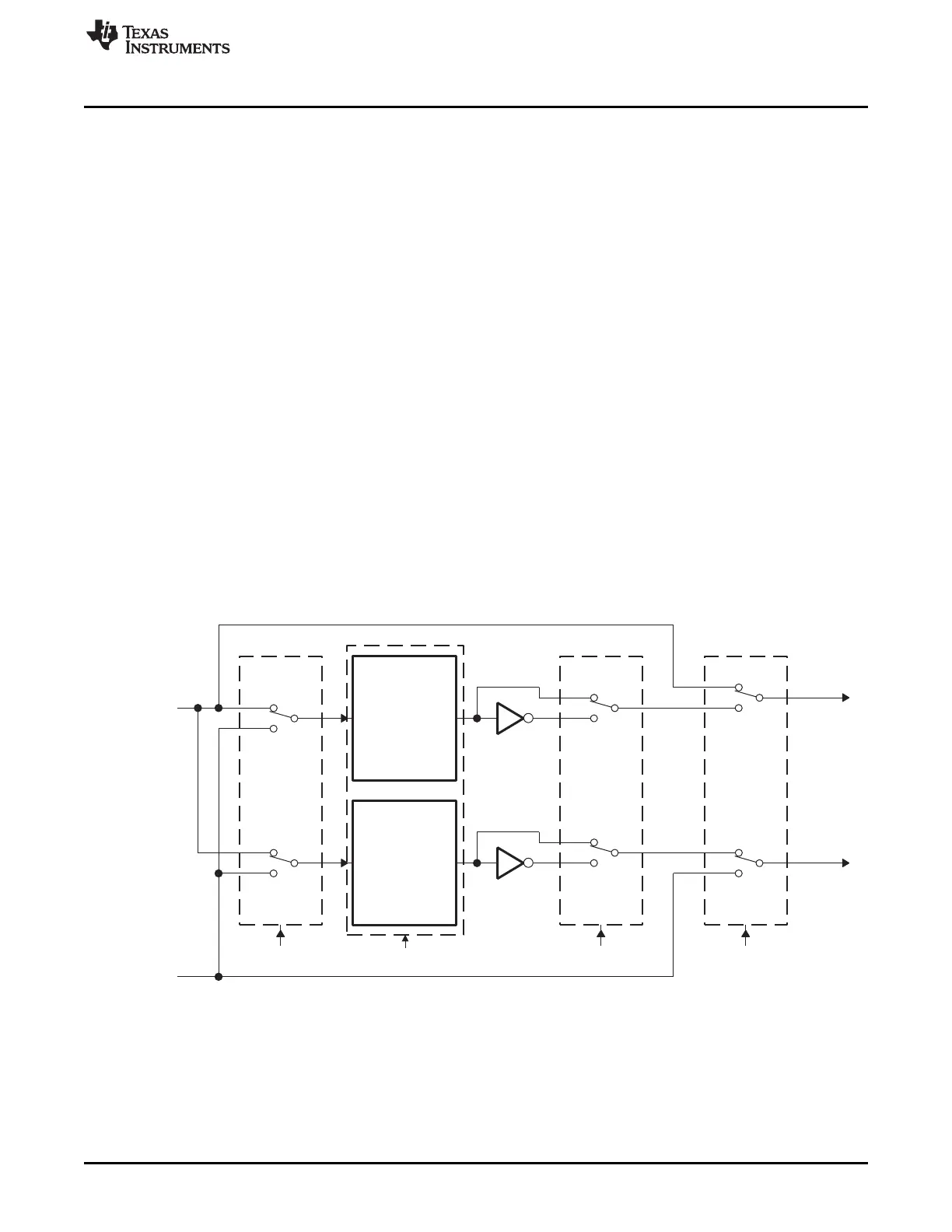
35.2.5.3 Operational Highlights for the Dead-Band Submodule
The following sections provide the operational highlights.
The dead-band submodule has two groups of independent selection options as shown in Figure 35-28.
• Input Source Selection:
The input signals to the dead-band module are the EPWMxA and EPWMxB output signals from the
action-qualifier. In this section they will be referred to as EPWMxA In and EPWMxB In. Using the
DBCTL[IN_MODE) control bits, the signal source for each delay, falling-edge or rising-edge, can be
selected:
– EPWMxA In is the source for both falling-edge and rising-edge delay. This is the default mode.
– EPWMxA In is the source for falling-edge delay, EPWMxB In is the source for rising-edge delay.
– EPWMxA In is the source for rising edge delay, EPWMxB In is the source for falling-edge delay.
– EPWMxB In is the source for both falling-edge and rising-edge delay.
• Half Cycle Clocking:
The dead-band submodule can be clocked using half cycle clocking to double the resolution (i.e.
counter clocked at 2× TBCLK)
• Output Mode Control:
The output mode is configured by way of the DBCTL[OUT_MODE] bits. These bits determine if the
falling-edge delay, rising-edge delay, neither, or both are applied to the input signals.
• Polarity Control:
The polarity control (DBCTL[POLSEL]) allows you to specify whether the rising-edge delayed signal
and/or the falling-edge delayed signal is to be inverted before being sent out of the dead-band
submodule.
Figure 35-28. Configuration Options for the Dead-Band Submodule

 Loading...


