Set
Latch
Clear
TZCLR[DCAEVT2]
DCAEVT2.inter
TZEINT[DCAEVT2]
TZFLG[DCAEVT2]
DCAEVT2.force
1
0
Sync
TBCLK
Async
1
0
DCACTL[EVT2SRCSEL]
DCEVTFILT
DCAEVT2
DCACTL[EVT2FRCSYNCSEL]
TZFRC[DCAEVT2]
DCACTL[EVT1SYNCE]
DCAEVT1.sync
DCACTL[EVT1SOCE]
DCAEVT1.soc
Set
Latch
Clear
TZCLR[DCAEVT1]
DCAEVT1.inter
TZEINT[DCAEVT1]
TZFLG[DCAEVT1]
DCAEVT1.force
1
0
Sync
TBCLK
Async
1
0
DCACTL[EVT1SRCSEL]
DCEVTFILT
DCAEVT1
DCACTL[EVT1FRCSYNCSEL]
TZFRC[DCAEVT1]
www.ti.com
ePWM Submodules
2051
SPNU563A–March 2018
Submit Documentation Feedback
Copyright © 2018, Texas Instruments Incorporated
Enhanced Pulse Width Modulator (ePWM) Module
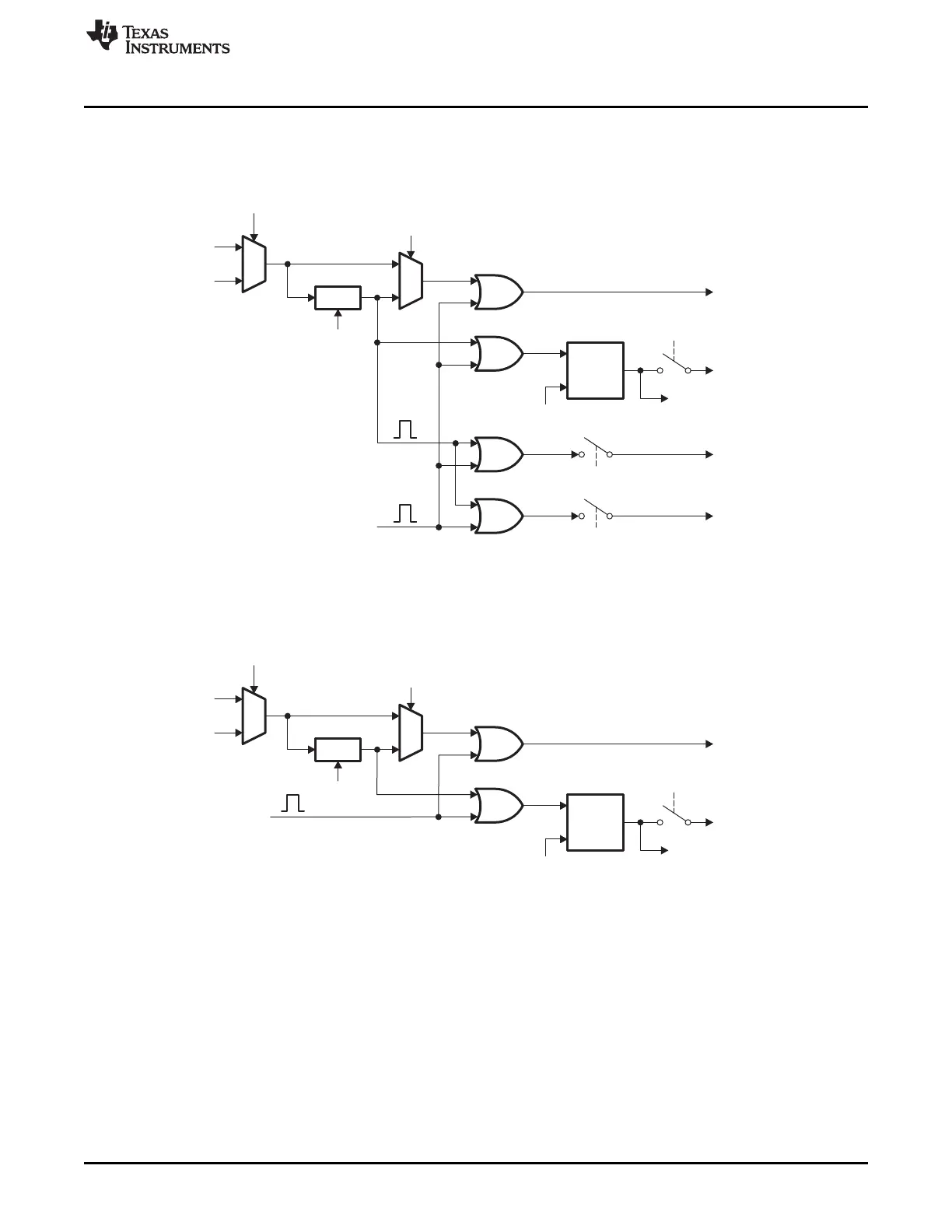
Figure 35-45 and Figure 35-46 show how the DCAEVT1, DCAEVT2, or DCEVTFILT signals are
processed to generate the digital compare A event force, interrupt, soc and sync signals.
Figure 35-45. DCAEVT1 Event Triggering
Figure 35-46. DCAEVT2 Event Triggering

 Loading...


