CTRL
11
00 00
CTRL
CTRL
overflow
www.ti.com
Module Operation
2161
SPNU563A–March 2018
Submit Documentation Feedback
Copyright © 2018, Texas Instruments Incorporated
RAM Trace Port (RTP)
37.2.3.3 Cortex-R5 Specifics
Considerations/Restrictions
• Reading and writing from/to Level 2 RAMs which is declared Cacheable can result in RAM traces that
do not correspond to the software's original intent.
• A store instruction to Non-cacheable, or write-through Normal memory might not result in an AXI
transfer to the Level 2 RAMs or peripherals because of the merging of store in the internal buffers.
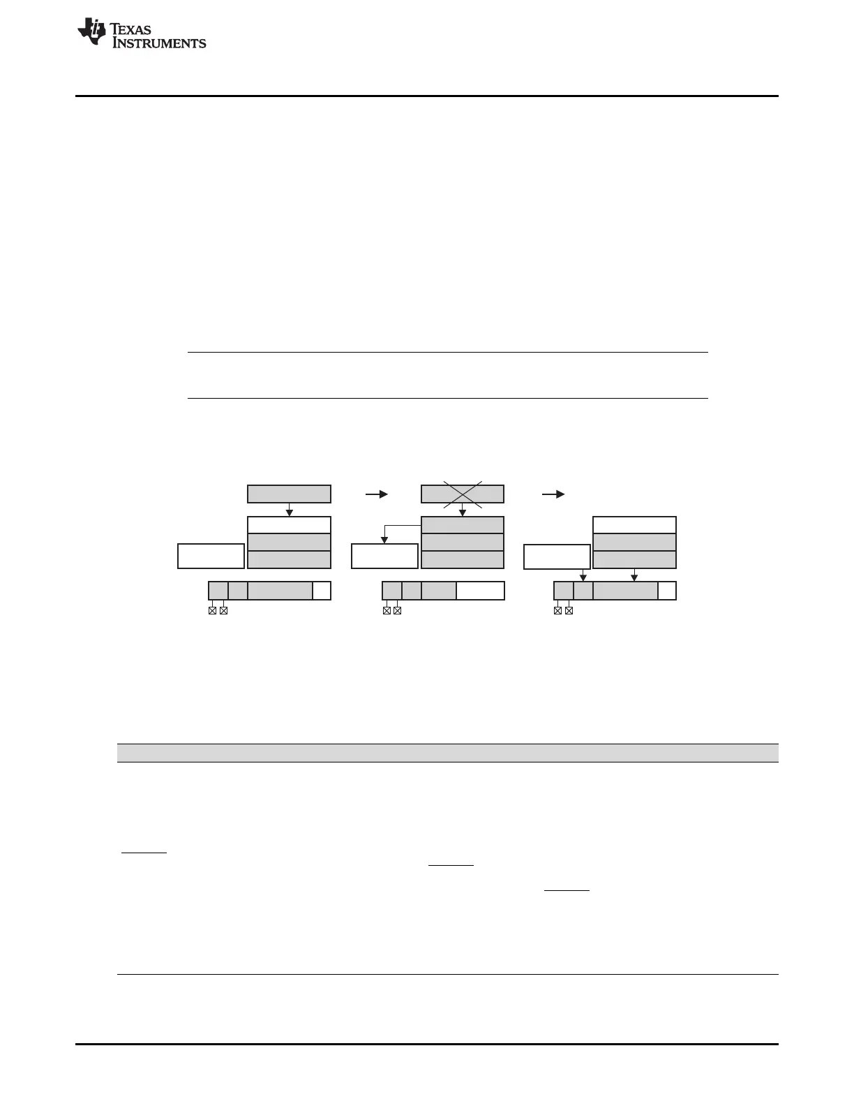
37.2.4 Overflow/Empty Handling
In case the application does RAM accesses faster than the FIFO can be emptied via the external pin
interface, the FIFO can overflow. You can choose whether the program execution/data transfer should be
suspended, or an overflow should be signaled in the status bits of the next, to be transmitted, message of
this particular FIFO. If program execution is resumed, the data will be lost. The overflow will not be
signaled in the message that is already in the serializer and being transmitted when the overflow occurs.
NOTE: The status information will only be transmitted in Trace Mode, since the Direct Data Mode
packet does not contain any status information.
When an overflow in a FIFO occurs, the corresponding bit in the RTP global status register (RTPGSR) will
be set.
Figure 37-6. FIFO Overflow Handling
37.2.5 Signal Description
Table 37-6 lists the signals of the RTP.
Table 37-6. RTP Signals
Signal Description
RTPCLK This clock signal is used to clock out the data of the serializer. Depending on the CONTCLK bit,
the clock can be suspended between packets or it can be free running. The RTPCLK frequency
can be adjusted by the PRESCALER bits (see RTP global control register (RTPGLBCTRL).
RTPSYNC The module provides a packet-sync signal. This signal will go high on the rising edge of RTPCLK
and will be valid for one RTPCLK cycle to synchronize external hardware to the data stream. The
RTPSYNC pulse will be generated for each new packet.
RTPENA This signal is an input and can be used by external hardware to stop the data transmission
between packets. When the RTPENA signal goes high, the RTP will finish the current packet
transmission and then stop. Once the signal is pulled low again, the RTP will resume the transfer
if data is still present in the serializer or FIFOs. The RTPENA signal does not have to be used for
proper module operation. It can be used in GIO mode if the external hardware cannot generate
this signal. Overflows of the external system cannot be handled in this case.
RTPDATA[15:0] These pins are used to do the actual data transfer. Data changes with the rising edge of RTPCLK.
The port can be configured for different widths (PW[1:0]). The minimum port width supported is 2
pins. See Table 37-10 which pins are used for the port.

 Loading...


