DEST[1] SIZE[1]
ADDR[15] ADDR[11]
ADDR[7]
ADDR[3]
DATA[7]
DATA[3]
DEST[0]
ADDR[13]
ADDR[6] ADDR[2] DATA[2]DATA[6]
DATA[5]
DATA[4]
ADDR[9]
ADDR[5]
ADDR[1] DATA[1]
ADDR[4]
ADDR[0] DATA[0]
SIZE[0]
ADDR[14] ADDR[10]
ADDR[12] ADDR[8]
STAT[1]
STAT[0]
ADDR[17]
ADDR[16]
RTPCLK
RTPSYNC
RTPDATA[0]
RTPDATA[1]
RTPDATA[2]
RTPDATA[3]
RTPSYNC
RTPDATA
RTPCLK
RTPENA
Packet1
Packet2
Packet3
Packet4
Packet1
Packet2
Module Operation
www.ti.com
2162
SPNU563A–March 2018
Submit Documentation Feedback
Copyright © 2018, Texas Instruments Incorporated
RAM Trace Port (RTP)
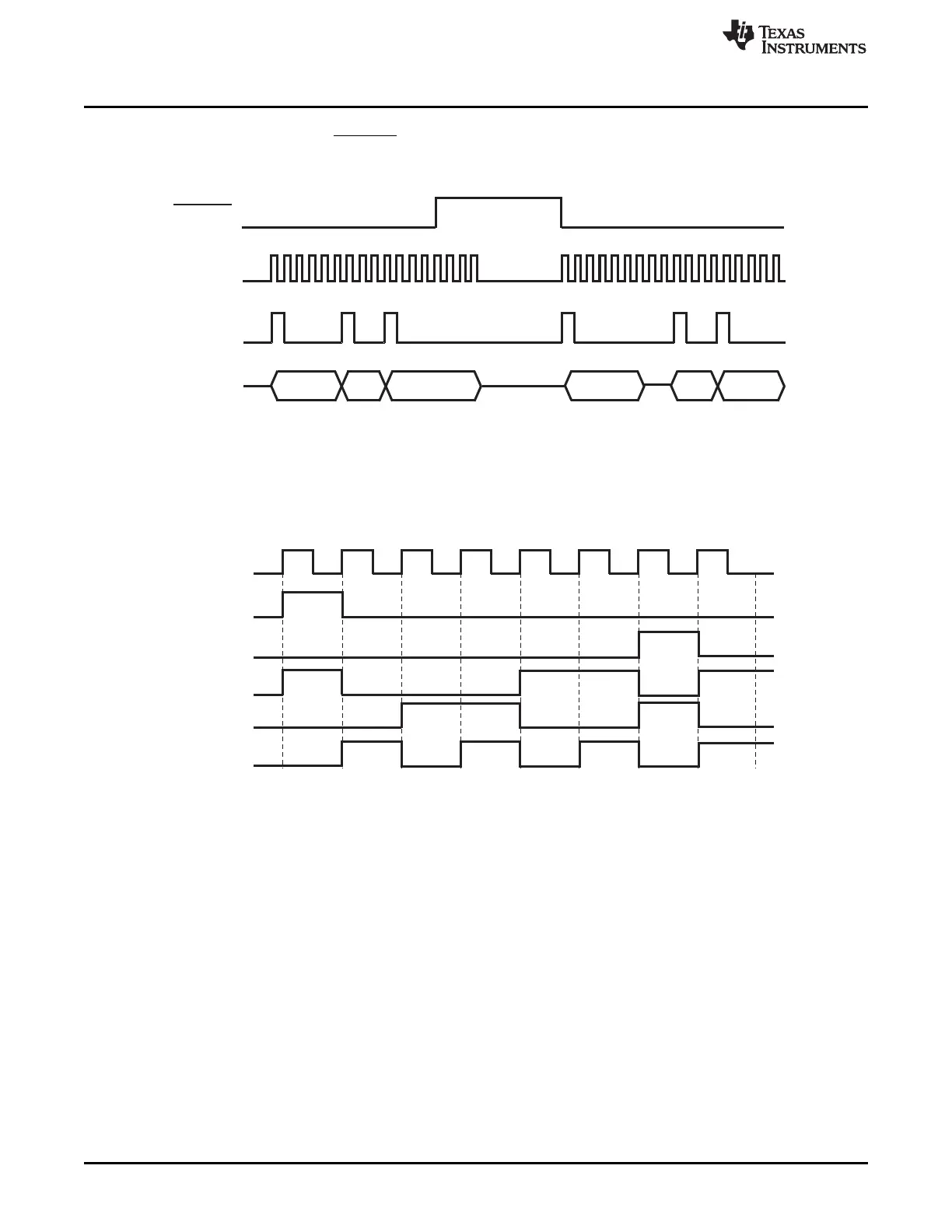
Figure 37-7 shows an example of multiple packet transmissions in Trace Mode with an interruption
between packets because of RTPENA pulled high.
Figure 37-7. RTP Packet Transfer with Sync Signal
Figure 37-8 shows an example of a 4-bit data port with 8-bit write data (A5h) written into RAM1 (address
12345h) with no overflow in trace mode.
Figure 37-8. Packet Format in Trace Mode
37.2.6 Data Rate
The module is configurable to support different RTPCLK frequencies. See the device datasheet for the
maximum supported frequency. HCLK will be prescaled to achieve the desired RTPCLK frequency. The
prescaler supports prescale values from 1 to 8, using the RTP global control register (RTPGLBCTRL).
The effective bandwidth depends on the configuration of the module and the average data width
transmitted in the packets.

 Loading...


