Memory System
DMA ControllerTimer
DMA channel 0
DMA channel 31
Ch1
PSA Reg
CRC Reg
Ch4
CRC Reg
PSA Reg
Sector 1
Sector 2
Sector n
DMA channel p
DMA channel q
.
DMA Request Event Sync.
CRC
Controller
HW DMA Req
one
block
www.ti.com
Module Operation
633
SPNU563A–March 2018
Submit Documentation Feedback
Copyright © 2018, Texas Instruments Incorporated
Cyclic Redundancy Check (CRC) Controller Module
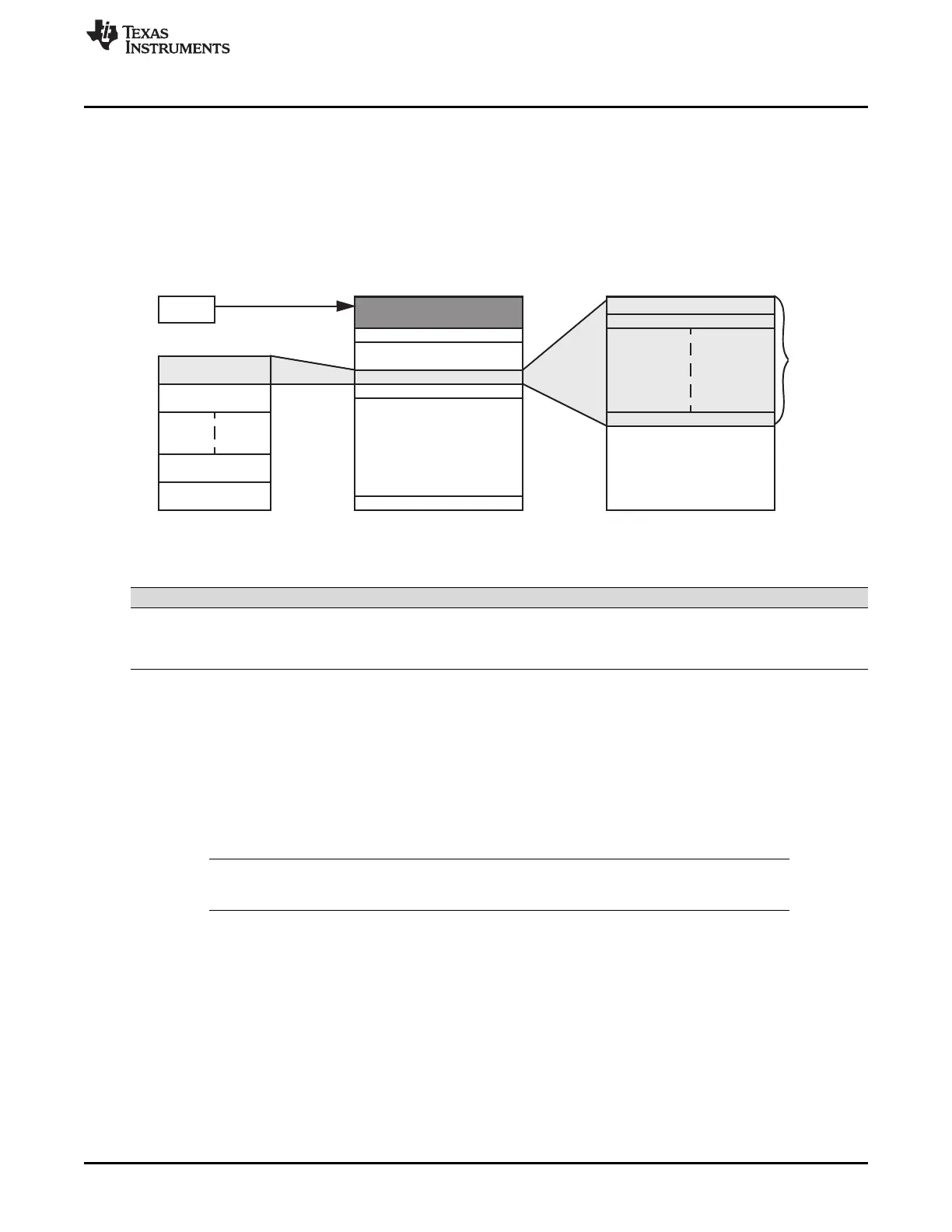
18.2.7.3 Semi-CPU Mode Using Hardware Timer Trigger
During semi-CPU mode, no DMA request is generated by CRC controller. Therefore, no DMA channel is
allocated to update CRC Value Register. CPU should not read from CRC Value Register in semi-CPU
mode as it contains stale value. Note that no signature verification is performed at all during this mode.
Similar to AUTO mode, either by hardware or by software DMA request can be used as a trigger for data
patterns transfer. Figure 18-5 illustrates the DMA setup using semi-CPU mode with hardware timer trigger.
Figure 18-5. Semi-CPU Mode With Hardware Timer Trigger
Table 18-1. CRC Modes in Which DMA Request and Counter Logic are Active or Inactive
Mode DMA Request Pattern Counter Sector Counter Timeout Counter
AUTO Active Active Active Active
Semi-CPU Inactive Active Active Active
Full-CPU Inactive Inactive Inactive Inactive
18.2.8 Pattern Count Register
There is a 20-bit data pattern counter for every CRC channel. The data pattern counter is a down counter
and can be pre-loaded with a programmable value stored in the Pattern Count Register. When the data
pattern counter reaches zero, a compression complete interrupt is generated in Semi-CPU mode and an
automatic signature verification is performed in AUTO mode. In AUTO only, DMA request is generated to
trigger the DMA controller to update the CRC Value Register.
NOTE: The data pattern count should be divisible by the total transfer count as programmed in DMA
controller. The total transfer count is the product of element count and frame count.
18.2.9 Sector Count Register/Current Sector Register
Each channel contains a 16 bit sector counter. The sector count register stores the number of sectors.
Sector counter is a free running counter and is incremented by one each time when one sector of data
patterns is compressed. When the signature verification fails, the current value stored in the sector
counter is saved into current sector register. If signature verification fails, CPU can read from the current
sector register to identify the sector which causes the CRC mismatch. To aid and facilitate the CPU in
determining the cause of a CRC failure, it is advisable to use the following equation during CRC and DMA
setup:
CRC Pattern Count × CRC Sector Count = DMA Element Count × DMA Frame Count

 Loading...


