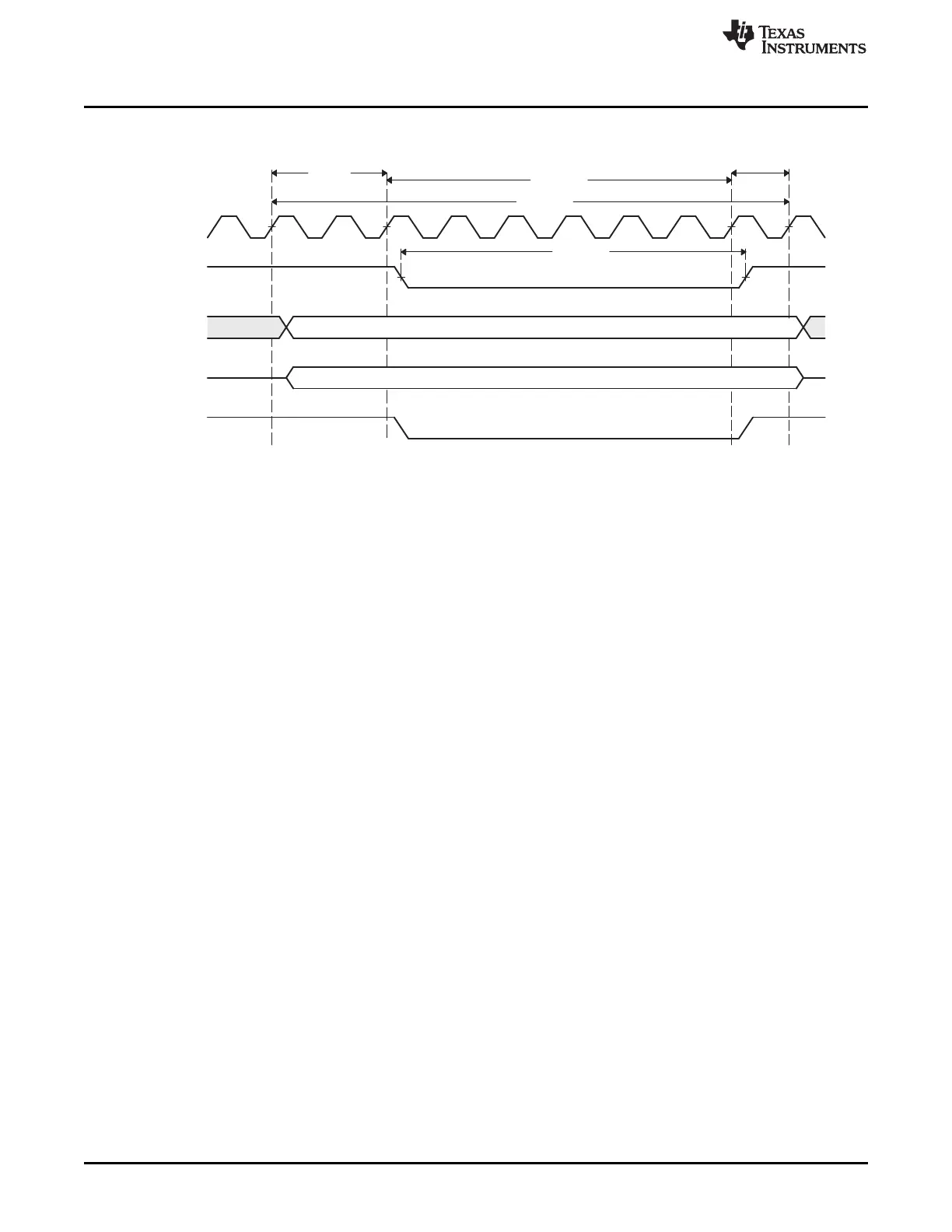
Setup
Strobe
Hold
t
AVAV
t
ELEH
Data
Address
EMIF_CLK
EMIF_nCS[n]
EMIF_A/
EMIF_BA
EMIF_D
EMIF_nWE
Example Configuration
www.ti.com
846
SPNU563A–March 2018
Submit Documentation Feedback
Copyright © 2018, Texas Instruments Incorporated
External Memory Interface (EMIF)
Figure 21-33. LH28F800BJE-PTTL90 to EMIF Write Timing Waveforms
The R_STROBE field should be set to meet the following equation:
R_STROBE >= (t
D
+ t
ELQV
+ t
SU
) × f
EMIF_CLK
- 1
R_STROBE >= (7 ns + 90 ns + 6.5 ns) × 100 MHz - 1
R_STROBE >= 9.35
R_STROBE = 10
The R_HOLD field must be large enough to satisfy the EMIF Data hold time, t
H
:
R_HOLD > = t
H
× f
EMIF_CLK
- 1
R_HOLD >= 1 ns × 100 MHz - 1
R_HOLD >= -0.9
The R_HOLD field must also combine with the TA field to satisfy the Flash's nCE High to Output in High
Impedance time, t
EHQZ
:
R_HOLD + TA >= (t
D
+ t
EHQZ
) × f
EMIF_CLK
- 2
R_HOLD + TA >= (7 ns + 55 ns) × 100 MHz - 2
R_HOLD + TA >= 4.2
The largest value that can be programmed into the TA field is 3h, therefore the following values can be
used:
R_HOLD = 2
TA = 3
For Writes, the W_STROBE field should be set to satisfy the Flash's nCE Pulse Width constraint, t
ELEH
:
W_STROBE >= t
ELEH
× f
EMIF_CLK
- 1
W_STROBE >= 50 ns × 100 MHz - 1
W_STROBE >= 4

 Loading...


