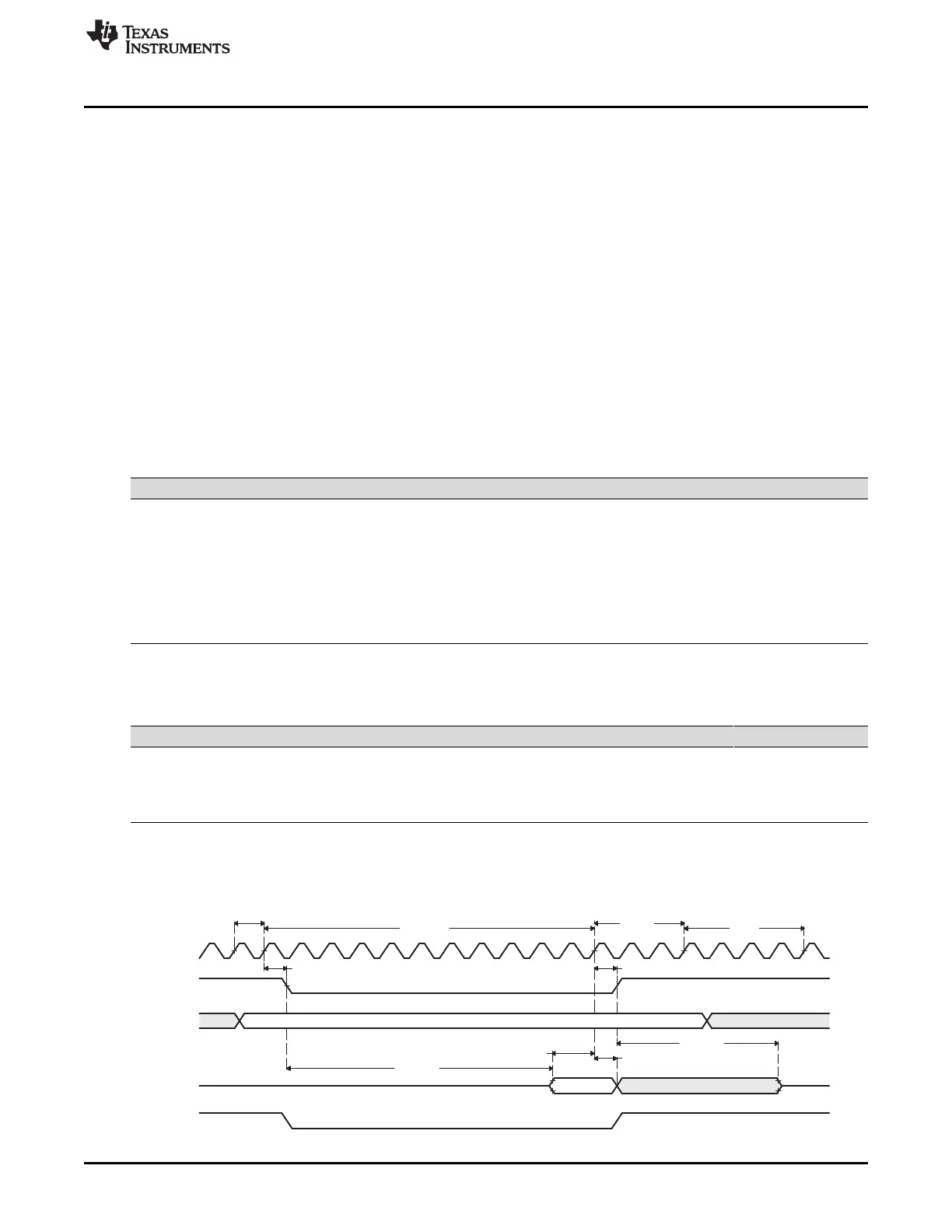
Setup
Strobe
Hold
TA
t
D
t
D
t
ELQV
t
H
t
SU
t
EHQZ
Data
EMIF_CLK
EMIF_nCS[n]
EMIF_A/
EMIF_BA
EMIF_D
EMIF_nOE
www.ti.com
Example Configuration
845
SPNU563A–March 2018
Submit Documentation Feedback
Copyright © 2018, Texas Instruments Incorporated
External Memory Interface (EMIF)
21.4.2.2 Configuring the Flash Interface
This section describes how to configure the EMIF to interface with the two of SHARP LH28F800BJE-
PTTL90 8Mb Flash memory with a clock frequency of f
EMIF_CLK
= 100 MHz. The example assumes that one
flash is connected to EMIF_nCS2 and the other to EMIF_nCS3.
21.4.2.2.1 Asynchronous 1 Configuration Register (CE2CFG) Settings for the EMIF to LH28F800BJE-
PTTL90 Interface
The asynchronous 1 configuration register (CE2CFG) and asynchronous 2 configuration register
(CE3CFG) are the only registers that is necessary to program for this asynchronous interface (assuming
that one Flash is connected to EMIF_nCS[2] and the other to EMIF_nCS[3]. The SS bit (in both registers)
should be set to 1 to enable Select Strobe Mode and the ASIZE field (in both registers) should be set to 1
to select a 16-bit interface. The other fields in this register control the shaping of the EMIF signals, and the
proper values can be determined by referring to the AC Characteristics in the Flash datasheet and the
device datasheet. Based on the following calculations, a value of 8862 25BDh should be written to
CE2CFG. Table 21-42 and Table 21-43 show the pertinent AC Characteristics for reads and writes to the
Flash device, and Figure 21-32 and Figure 21-33 show the associated timing waveforms. Finally,
Figure 21-34 shows programming the CEnCFG (n = 2, 3) with the calculated values.
Table 21-42. AC Characteristics for a Read Access
AC Characteristic Device Definition Min Max Unit
t
SU
EMIF Setup time, read EMIF_D before EMIF_CLK
high
6.5 ns
t
H
EMIF Data hold time, read EMIF_D after EMIF_CLK
high
1 ns
t
D
EMIF Output delay time, EMIF_CLK high to output
signal valid
7 ns
t
ELQV
Flash nCE to Output Delay 90 ns
t
EHQZ
Flash nCE High to Output in High Impedance 55 ns
Table 21-43. AC Characteristics for a Write Access
AC Characteristic Device Definition Min Max Unit
t
AVAV
Flash Write Cycle Time 90 ns
t
ELEH
Flash nCE Pulse Width Low 50 ns
t
EHEL
Flash nCE Pulse Width High (not shown in
Figure 21-33)
30 ns
Figure 21-32. LH28F800BJE-PTTL90 to EMIF Read Timing Waveforms

 Loading...


