HR
prescaler
Loop resolution
prescaler
(3 bits)
(6 bits)
VCLK2
Loop resolution
clock
HR
clock
www.ti.com
N2HET Functional Description
967
SPNU563A–March 2018
Submit Documentation Feedback
Copyright © 2018, Texas Instruments Incorporated
High-End Timer (N2HET) Module
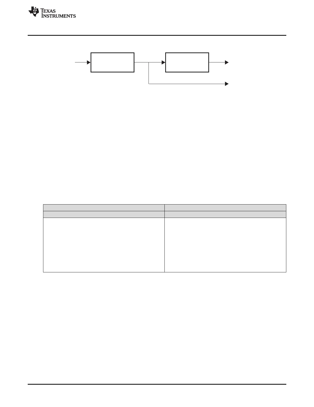
Figure 23-7. Prescaler Configuration
The following abbreviations and relations are used in this document:
1. hr: high resolution prescale factor (1, 2, 3, 4,..., 63, 64)
2. lr: loop resolution prescale factor (1, 2, 4, 8, 16, 32, 64,128)
3. ts: Time slots (cycles) available for instruction execution per loop. ts = hr x lr
4. HRP = high resolution clock period HRP = hr × T
VCLK2
(ns)
5. LRP = loop resolution clock period LRP = lr × HRP (ns)
The loop resolution period (LRP) must be selected to be larger than the number of Time slots (VCLK2
cycles) required to complete the worst-case execution path through the N2HET program. Otherwise a
program overflow condition may occur (see Section 23.2.1.4). Because of the relationship of time slots to
the hr and lr prescalers as described in item 3 above, increasing either hr or lr increases the number of
time slots available for program execution. However, lr would typically be increased first, since increasing
hr results in a decrease in timer resolution since it reduces the clock to the High Resolution IO structures.
The divide rates hr and lr can be defined in the HETPFR register. Table 23-5 lists the bit field encodings
for the prescale options.
Table 23-5. Prescale Factor Register Encoding
LRPFC - Loop Resolution HRPFC - High Resolution
HETPFR[10:8] Prescale Factor lr HETPFR[5:0] Prescale Factor hr
000 /1 000000 /1
001 /2 000001 /2
010 /4 000010 /3
011 /8 000011 /4
100 /16 : :
101 /32 111101 /62
110 /64 111110 /63
111 /128 111111 /64

 Loading...


