HR 0
HR 1
X
X
Output
Buffer
Output
Buffer
Pin 0
Pin 1
Loopback values will NOT be
seen on the pins in Digital
Loopback Mode
LBPDIR [0] value
determines which HR
block is input and which
is output
LBSEL[0] value
determines whether or
not loopback is enabled
for these two blocks
www.ti.com
N2HET Functional Description
977
SPNU563A–March 2018
Submit Documentation Feedback
Copyright © 2018, Texas Instruments Incorporated
High-End Timer (N2HET) Module
23.2.5.7 Loop Back Mode
The loop back feature can be used by the application to monitor an N2HET output signal. For example, if
a PWM is generated by HR structure 0, then a PCNT instruction assigned to HR structure 1 can measure
back the pulse length or periods of the PWM output signal.
Loopback mode is activated between two high resolution structures by setting LBPSEL[x] to 1 in the
HETLBPSEL register for the corresponding structure pair. The direction of the loopback between the two
structures in the structure pair is determined by the value of LBPDIR[x] in the HETLBPDIR Register.
For example, if bit LBPSEL[0] is set to 1, then HR structures 0 and 1 will be internally connected in loop
back mode. If bit LBPDIR[0] is set to 0, then structure 0 will be the input and structure 1 will be the output.
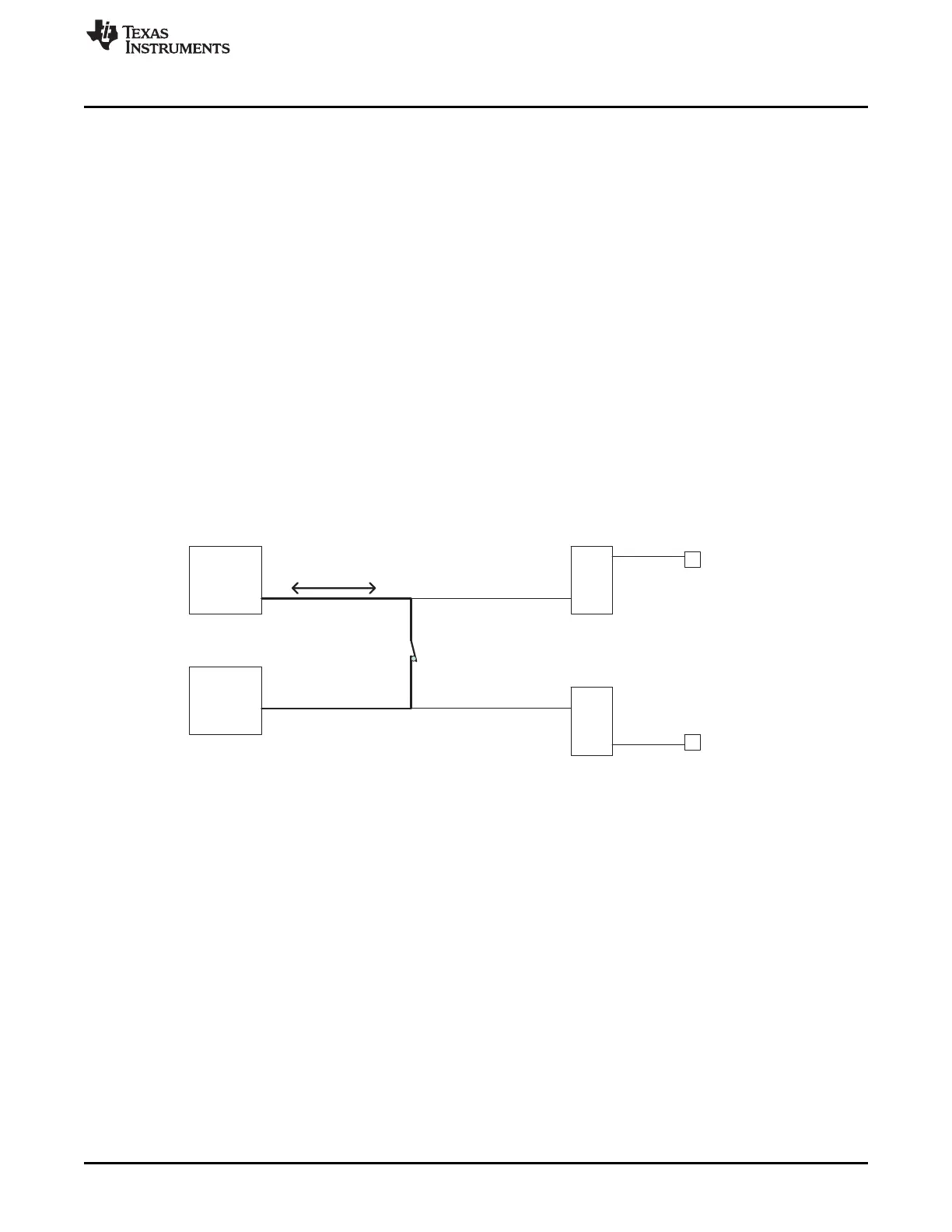
Digital Loopback
Digital loopback mode is enabled by setting LBPTYPE[x] to 0 in the HETLBPSEL register for the
corresponding structure pairs. In digital loopback mode, the structure pairs are connected directly and the
output buffers are bypassed. Therefore, the loopback values will NOT be seen on the corresponding pins.
Figure 23-16 shows an example of digital loopback between structures HR0 and HR1. LBSEL[0] has been
set to 1 to enable loopback between the two structures. LBTYPE[0] has been set to 0 to select digital
mode for the loopback pair. The LPBDIR[0] value will determine the direction of the loopback by selecting
which of the HR blocks is output, and which is input. The bold lines show the digital loopback path.
Figure 23-16. HR0 to HR1 Digital Loopback Logic: LBTYPE[0] = 0

 Loading...


