www.ti.com
N2HET Functional Description
979
SPNU563A–March 2018
Submit Documentation Feedback
Copyright © 2018, Texas Instruments Incorporated
High-End Timer (N2HET) Module
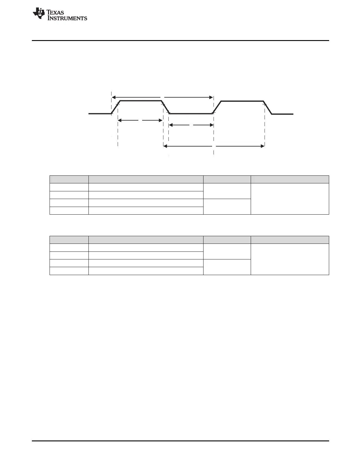
23.2.5.8 Edge Detection Input Timing
There are several timing requirements for input signals in order to be captured correctly by N2HET.
Figure 23-18 illustrates these requirements, with min and max values described in Table 23-7 (Loop
Resolution) and Table 23-8 (High Resolution).
Figure 23-18. N2HET Input Edge Detection
Table 23-7. Edge Detection Input Timing for Loop Resolution Instructions
Parameter # Description min max
1 Input Signal Period, rising edge to rising edge
> 2 (hr) (lr) t
c(VCLK2)
< 2
25
(hr) (lr) t
c(VCLK2)
2 Input Signal Period, falling edge to falling edge
3 Input Signal, high phase
> (hr) (lr) t
c(VCLK2)
4 Input Signal, high phase
Table 23-8. Edge Detection Input Timing for High Resolution Instructions
Parameter # Description min max
1 Input Signal Period, rising edge to rising edge
> (hr) (lr) t
c(VCLK2)
< 2
25
(hr) (lr) t
c(VCLK2)
2 Input Signal Period, falling edge to falling edge
3 Input Signal, high phase
> 2 (hr) t
c(VCLK2)
4 Input Signal, high phase
These are the N2HET architectural limitations. Actual limitations will be slightly different due to on chip
routing and IO buffer delays, usually by several nanoseconds. Be sure to consult the device datasheet for
actual timings that apply to that device. Also, certain devices place additional restrictions on which pins
support the high resolution timings of Table 23-8, if present these additional limitations will also be called
out in the device datasheet.
Note that the max limit in Table 23-7 and Table 23-8 is based on the counter range of a single N2HET
instruction. The max value could be extended by employing an additional N2HET instruction to keep track
of counter overflows of the input counter / capture instruction.
23.2.5.9 PWM Generation Example 1 (in HR Mode)
The following example shows how an ECMP instruction works in high resolution mode. The example
assumes a VCLK2 of 32 MHz and the following values for the prescale divide rates (hr and lr), number of
time slots (ts), high and loop resolution period (HRP and LRP):
hr = 2, lr = 4, ts = hr × lr = 8
HRP = hr / VCLK2 = 2 / 32 MHz = 62.5 ns
LRP = (hr × lr) / VCLK2 = 8 / 32 MHz = 250 ns
With ts = 8, there are eight time slots available for the program execution, which in this case will consist of
one CNT and one ECMP instruction as shown below. The data field of the ECMP instruction is the 32-bit
compare value, whereby the lower 7 bits represent the high resolution compare field.

 Loading...


