HR clock
ECMP
Pin
action
Opposite
pin action
LR clock
LR clock HRclock
PWCNT
Pin
action
Opposite
pin action
www.ti.com
N2HET Functional Description
981
SPNU563A–March 2018
Submit Documentation Feedback
Copyright © 2018, Texas Instruments Incorporated
High-End Timer (N2HET) Module
23.2.5.10 PWM Generation Example 2 (in HR Mode)
The MCMP instruction can also be used in HR mode. In this case operation is exactly the same as for the
ECMP instruction except that the 25-bit low resolution is now the result of a magnitude compare (greater
or equal) rather than an equality compare. When the 25-bit (loop resolution) magnitude compare matches,
the HR compare value will be loaded from the 7 lower bits of the instruction data field to the HR counter.
At the next loop resolution clock, the HR counter will count down at the HR clock frequency and perform
the pin action when it reaches zero.
The MCMP instruction avoids the missing pulse problem of the ECMP instruction (see previous example),
however the duty cycle of the signal might not be exact for one PWM period. The benefit of the MCMP is
that it avoids adding another instruction to do the duty cycle update synchronously.
23.2.5.11 Pulse Generation Example (in HR Mode)
The PWCNT instruction may also be used in HR mode to generate pulse outputs with HR width. It
generates a single pulse when the data field of the instruction is non-zero. It remains at the opposite pin
action when the data field is zero.
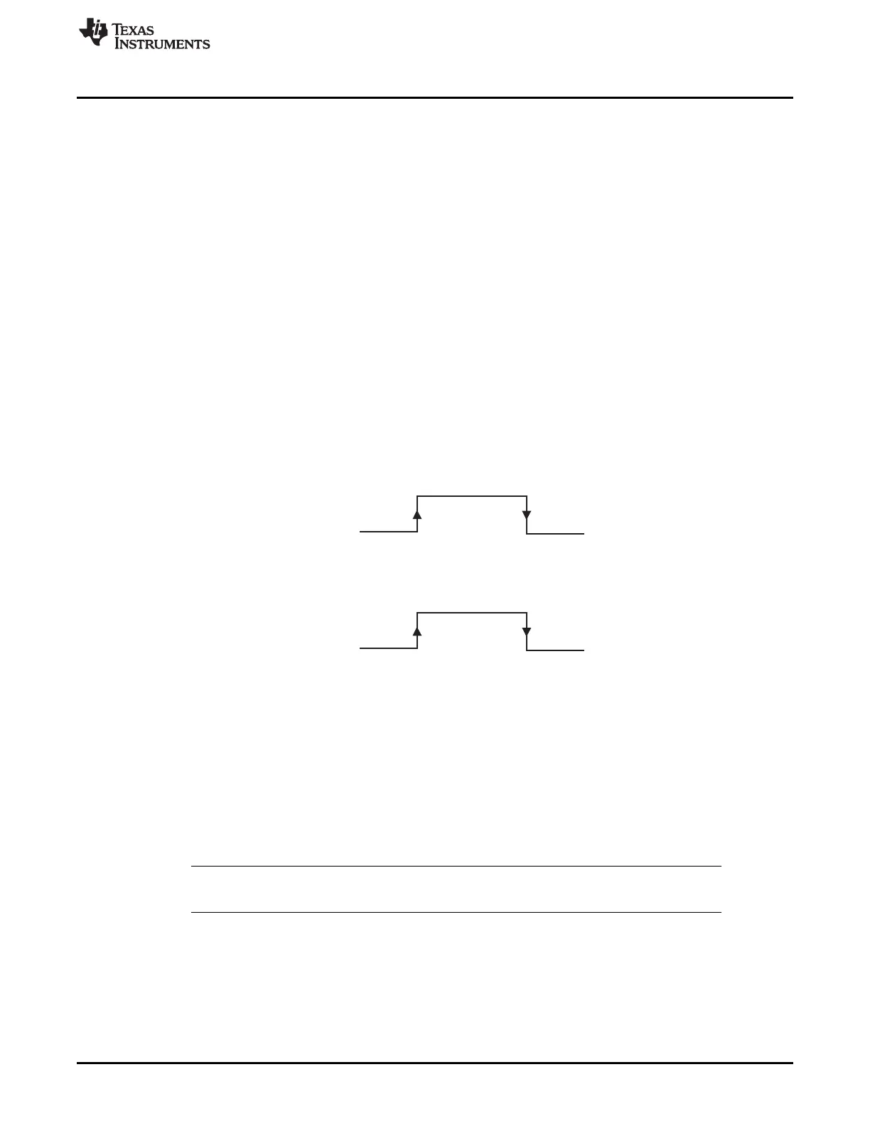
The PWCNT instruction operates conversely to the ECMP instruction. See Figure 23-20. For PWCNT, the
opposite pin action is synchronous with the HR clock and for ECMP the pin action is synchronous with the
HR clock. The PWCNT pin action is synchronous with the loop resolution clock.
Figure 23-20. High/Low Resolution Modes for ECMP and PWCNT
23.2.5.12 Pulse Measurement Example (in HR Mode)
The PCNT instruction captures HR measurement of the high/low pulse time or periods of the input. As
shown in Figure 23-21, at marker (1) the input goes HIGH and the HR counter immediately begins to
count. The counter increments and rolls over until the falling edge on the input pin, where it captures the
counter value into the HR capture register (marker (2)). The PCNT instruction begins counting when the
synchronized input signal goes HIGH and captures both the 25-bit data field and the HR capture register
into RAM when the synchronized input falls (marker (3)).
NOTE: The HR capture value written into RAM is shifted appropriately depending on the loop
resolution prescale divide rate (lr). (See also Section 23.2.3.2).

 Loading...


