HR clock
Loop res
clock
PCNT CF
HR counter
HR capt.
reg
PCNT DF
Input pin
Input pin
sync’d
X
0 1 2
0 1 2 3 0 1 2 3 0
0
X
3
X 1
1
2
3
HR clock
Loop res
clock
PCNT CF
HR counter
HR capt.
reg
PCNT DF
Input pin
Input pin
sync’d
X
0 1 2
0 1 2 3 0 1 2 3 0
0
X
1
X 2
1 2 3
N2HET Functional Description
www.ti.com
982
SPNU563A–March 2018
Submit Documentation Feedback
Copyright © 2018, Texas Instruments Incorporated
High-End Timer (N2HET) Module
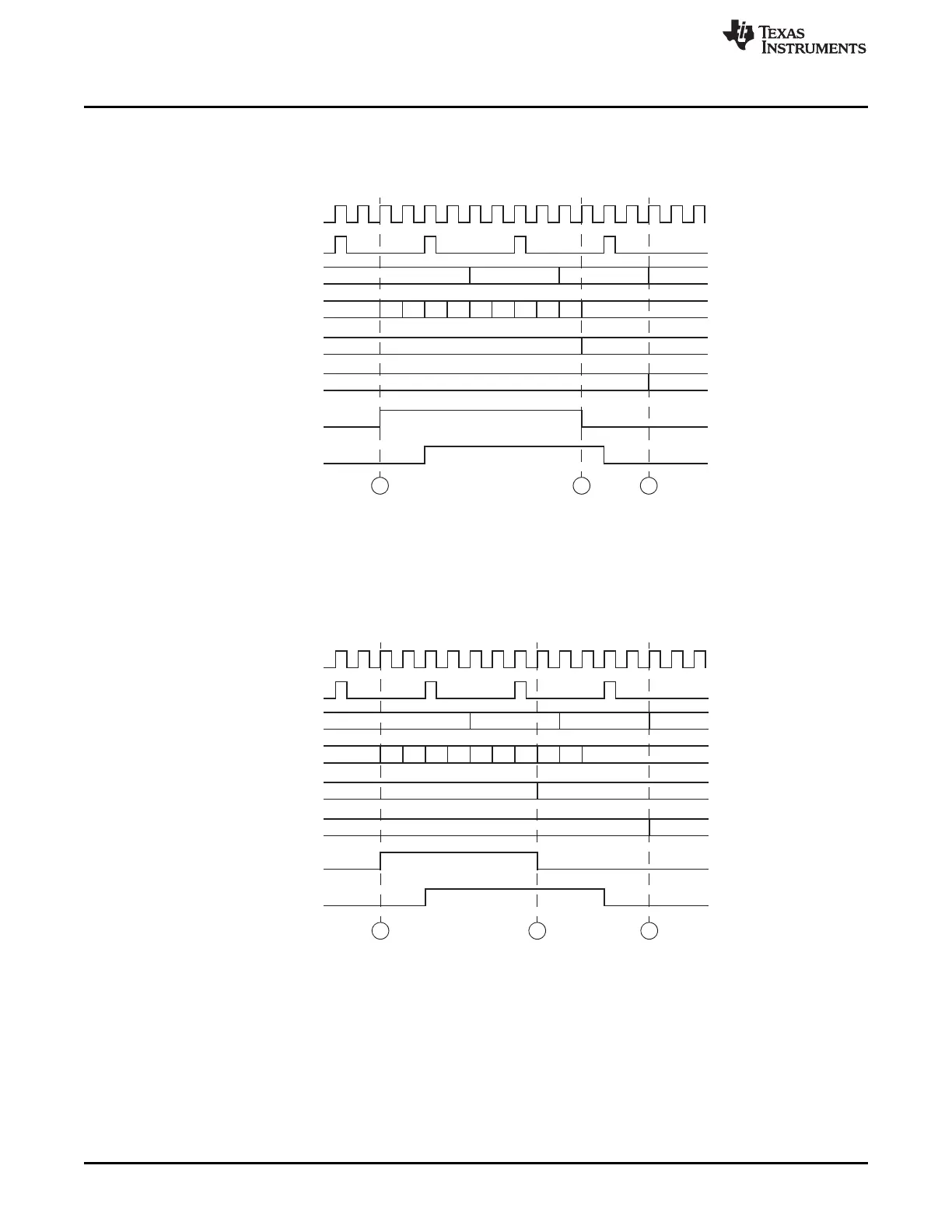
Figure 23-21 shows what happens when the capture edge arrives after the HR counter overflows. This
causes the incremented value to be captured by the PCNT instruction.
Figure 23-21. PCNT Instruction Timing (With Capture Edge After HR Counter Overflow)
Figure 23-22 shows what happens when the capture edge arrives before the HR counter overflows. This
causes the non-incremented value to be captured by the PCNT instruction.
Figure 23-22. PCNT Instruction Timing (With Capture Edge Before HR Counter Overflow)

 Loading...


