www.ti.com
FlexRay Module Registers
1403
SPNU563A–March 2018
Submit Documentation Feedback
Copyright © 2018, Texas Instruments Incorporated
FlexRay Module
Table 26-154. Channel Filter Control Bit Descriptions
CHA CHB
Transmit Buffer
transmit frame on
Receive Buffer
store frame received from
1 1
both channels
(static segment only)
channel A or B
(store first semantically valid frame, static segment
only)
1 0 channel A channel A
0 1 channel B channel B
0 0 no transmission ignore frame
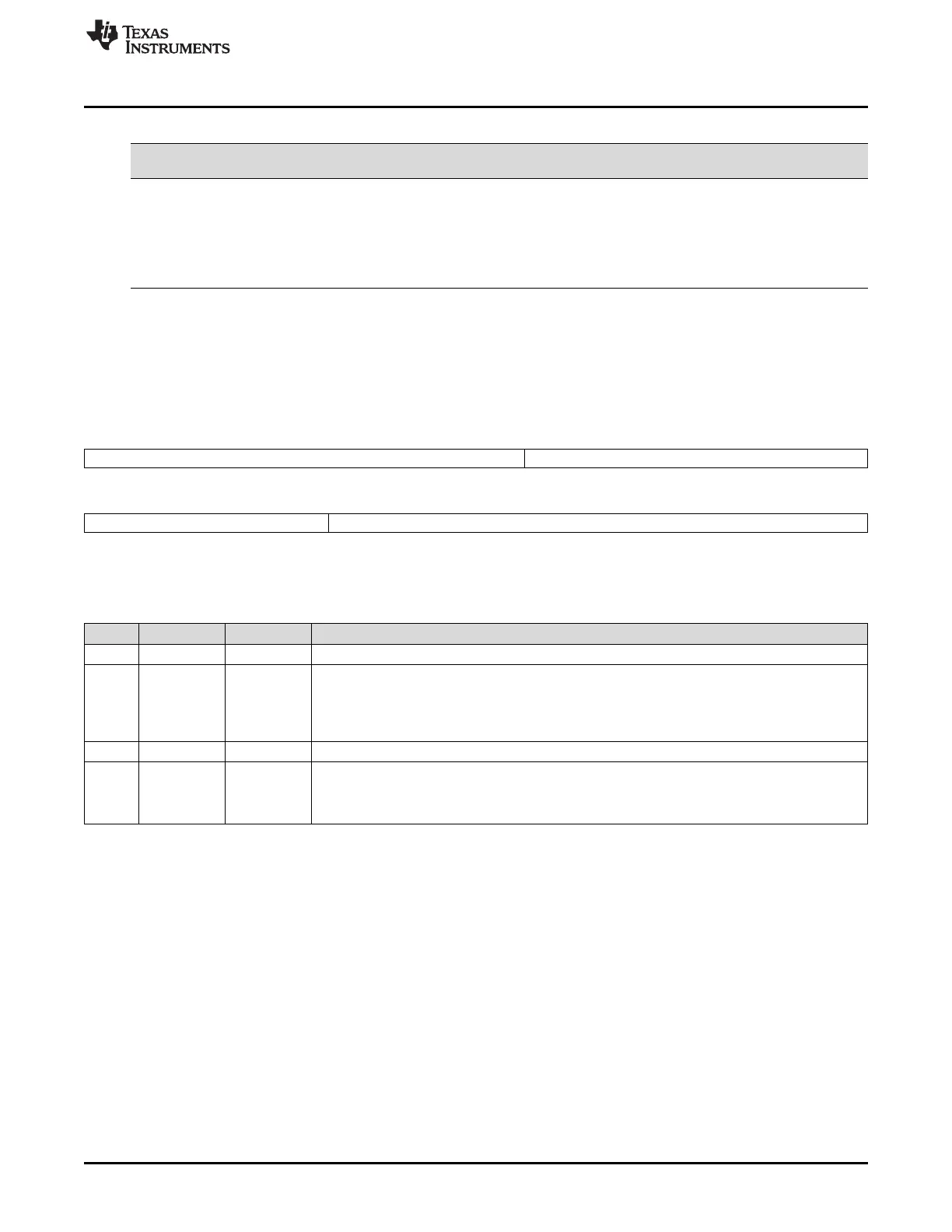
26.3.2.8.3 Write Header Section Register 2 (WRHS2)
Figure 26-182 and Table 26-155 illustrate this register.
Figure 26-182. Write Header Section Register 2 (WRHS2) [offset_CC = 504h]
31 23 22 16
Reserved PLC
R-0 R/W-0
15 11 10 0
Reserved CRC
R-0 R/W-0
LEGEND: R/W = Read/Write; R = Read only; -n = value after reset
Table 26-155. Write Header Section Register 2 (WRHS2) Field Descriptions
Bit Field Value Description
31-23 Reserved 0 Reads return 0. Writes have no effect.
22-16 PLC 0-7Fh Payload length configured. Length of data section (number of 2-byte words) as configured by the
host. During static segment the static frame data length as configured by SFDL in the MHD
configuration register defines the payload length for all static frames. If the payload length
configured by PLC is shorter than this value padding bytes are inserted to ensure that frames have
proper physical length. The padding pattern is logical 0.
15-11 Reserved 0 Reads return 0. Writes have no effect.
10-0 CRC 0-7FFh Header CRC. Receive Buffer: configuration not required. Transmit buffer: Header CRC calculated
and configured by the host. For calculation of the header CRC the payload length of the frame
send on the bus has to be considered. In static segment the payload length of all frames is
configured by MHDC.SFDL.

 Loading...


