System and Peripheral Control Registers
www.ti.com
158
SPNU563A–March 2018
Submit Documentation Feedback
Copyright © 2018, Texas Instruments Incorporated
Architecture
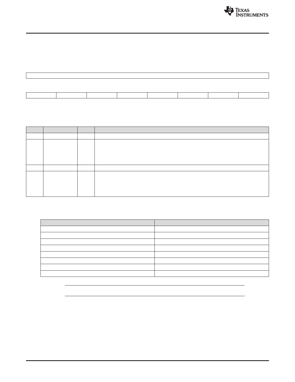
2.5.1.10 Clock Source Disable Register (CSDIS)
The CSDIS register, shown in Figure 2-17 and described in Table 2-28, controls and displays the state of
the device clock sources.
Figure 2-17. Clock Source Disable Register (CSDIS) (offset = 30h)
31 8
Reserved
R-0
7 6 5 4 3 2 1 0
CLKSR7OFF CLKSR6OFF CLKSR5OFF CLKSR4OFF CLKSR3OFF Reserved CLKSR1OFF CLKSR0OFF
R/WP-1 R/WP-1 R/WP-0 R/WP-0 R/WP-1 R-1 R/WP-1 R/WP-0
LEGEND: R/W = Read/Write; R = Read only; WP = Write in privileged mode only; -n = value after reset
Table 2-28. Clock Source Disable Register (CSDIS) Field Descriptions
Bit Field Value Description
31-8 Reserved 0 Reads return 0. Writes have no effect.
7-3 CLKSR[7-3]OFF Clock source[7-3] off.
0 Clock source[7-3] is enabled.
1 Clock source[7-3] is disabled.
Note: On wakeup, only clock sources 0, 4, and 5 are enabled.
2 Reserved 1 Reads return 1. Writes have no effect.
1-0 CLKSR[1-0]OFF Clock source[1-0] off.
0 Clock source[1-0] is enabled.
1 Clock source[1-0] is disabled.
Note: On wakeup, only clock sources 0, 4, and 5 are enabled.
Table 2-29. Clock Sources Table
Clock Source # Clock Source Name
Clock Source 0 Oscillator
Clock Source1 PLL1
Clock Source 2 Not Implemented
Clock Source 3 EXTCLKIN
Clock Source 4 Low Frequency LPO (Low Power Oscillator) clock
Clock Source 5 High frequency LPO (Low Power Oscillator) clock
Clock Source 6 PLL2
Clock Source 7 EXTCLKIN2
NOTE: Non-implemented clock sources should not be enabled or used.

 Loading...


