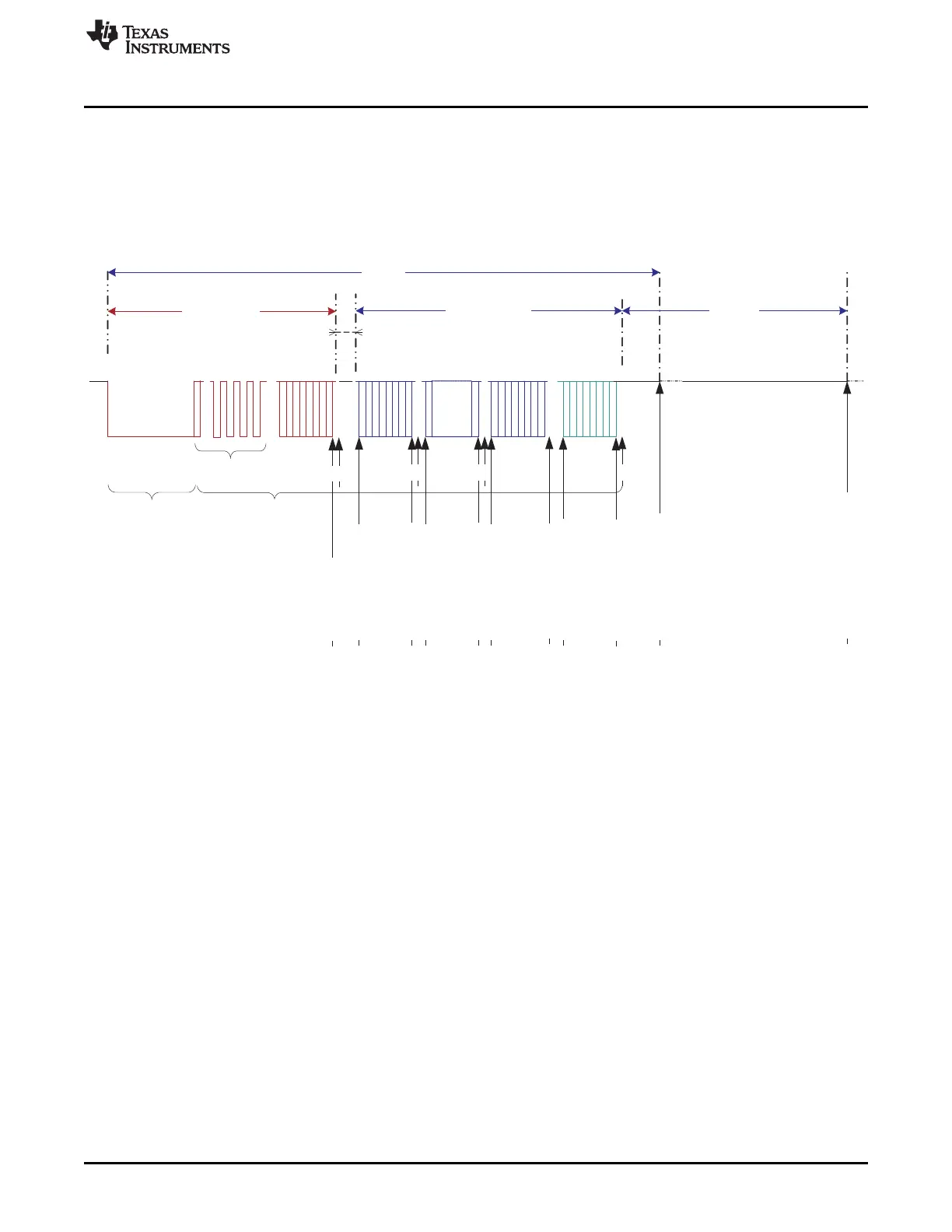
Sync Break Sync Field ID Field 1, 2, 3, ...8 Data Fields
Checksum
Master Header
Slave Response
In-frame space
T
FrameMax
T
Bus Idle (4s)
Parity Error Int.
ID Interrupt
No Response Error Int.
Timeout - Bus Idle (4s) Int.
ISF Error Int.
Physical Bus
Error Int.(Master)
FE
FE
Checksum Error Int.
RX Int. (multi-buffer/
last byte single buffer)
RX Int. (single buffer)
RX Int. (single buffer)
Overrun Error Int.
Bit Error Int.
FE
FE
TX Int. (single buffer)
TX Int. (single buffer)
TX Int. (single buffer)
TX Int. (multi buffer/
last byte single buffer)
Frame Error Int. (FE)
www.ti.com
LIN
1659
SPNU563A–March 2018
Submit Documentation Feedback
Copyright © 2018, Texas Instruments Incorporated
Serial Communication Interface (SCI)/ Local Interconnect Network (LIN)
Module
29.3.2 LIN Interrupts
LIN and SCI mode have a common Interrupt block as explained in Section 29.2.2. There are 16 interrupt
sources in the SCI/LIN module, with 8 of them being LIN mode only, as seen in Table 29-4.
A LIN message frame indicating the timing and sequence of the LIN interrupts that could occur is shown in
Figure 29-25.
Figure 29-25. LIN Message Frame Showing LIN Interrupt Timing and Sequence
29.3.3 LIN DMA Interface
LIN DMA Interface uses the SCI DMA interface logic. DMA requests for receive (RXDMA request) and
transmit (TXDMA request) are available for the SCI/LIN module. There are two modes for DMA transfers
depending on whether multi-buffer mode is enabled or not via the multi-buffer enable control bit (MBUF
MODE).
29.3.3.1 LIN Receive DMA Requests
In LIN mode, when the multi-buffer option is enabled, if a received response (up to eight data bytes) is
transferred to the receive buffers (RDy), then a DMA request is generated. If the multi-buffer option is
disabled, then DMA requests will be generated on a byte-per-byte basis until all the expected response
data fields are received. This DMA functionality is enabled and disabled using the SET RX DMA and CLR
RX DMA bits, respectively.
29.3.3.2 LIN Transmit DMA Requests
In LIN mode with the multi-buffer option enabled, after a transmission (up to eight data bytes stored in the
transmit buffer(s) TDy in the LINTD0 and LINTD1 registers), a DMA request is generated in order to
reload the transmit buffer for the next transmission. If the multi-buffer option is disabled, then DMA
requests will be generated on a byte-per-byte basis until all bytes are transferred. This DMA functionality
is enabled and disabled using the SET TX DMA and CLR TX DMA bits, respectively.

 Loading...


