SCI/LIN Control Registers
www.ti.com
1688
SPNU563A–March 2018
Submit Documentation Feedback
Copyright © 2018, Texas Instruments Incorporated
Serial Communication Interface (SCI)/ Local Interconnect Network (LIN)
Module
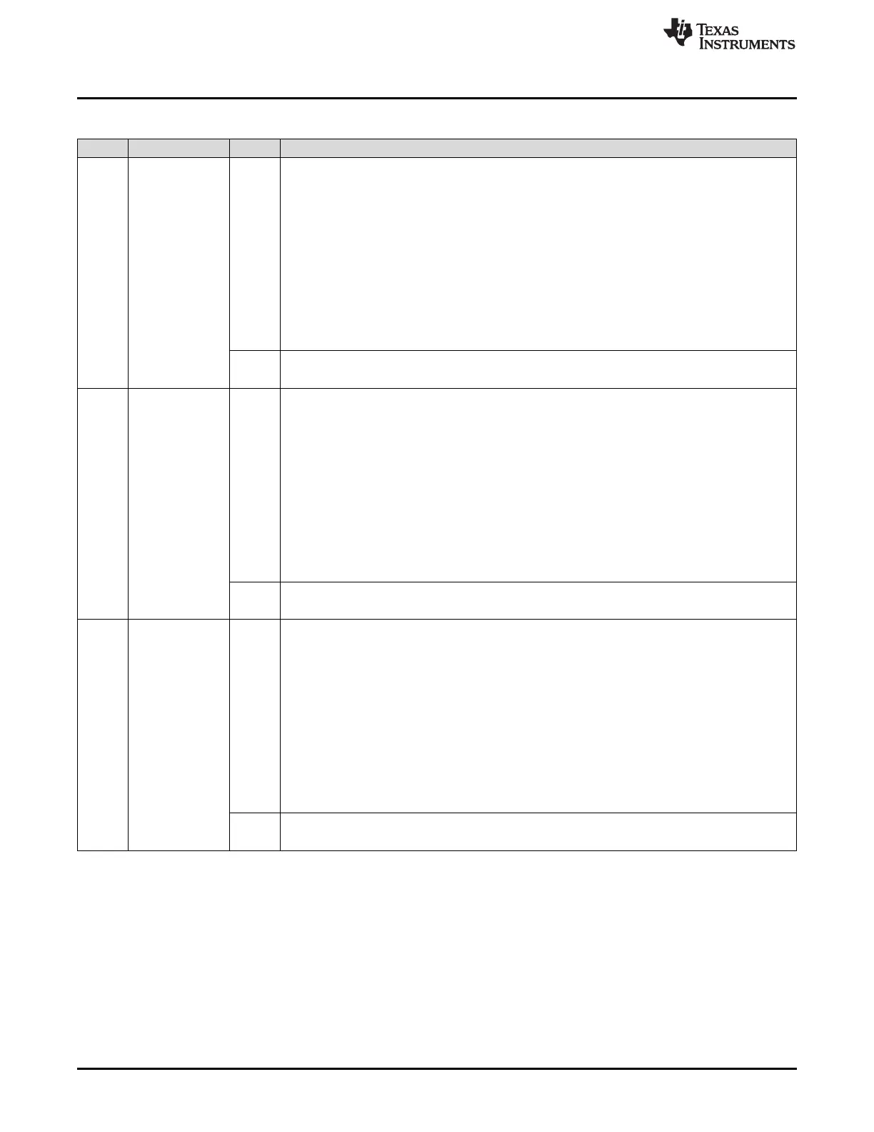
Table 29-20. SCI Flags Register (SCIFLR) Field Descriptions (continued)
Bit Field Value Description
29 CE Checksum error flag. This bit is effective in LIN mode only. This bit is set when a checksum error
has been detected by a receiving node. This error is detected by the TED logic. See
Section 29.3.1.8 for more information. The type of checksum to be used depends on the CTYPE bit
in SCIGCR1. The checksum error flag is cleared by the following:
• Setting of the SWnRST bit
• Setting of the RESET bit
• A system reset
• Writing a 1 to this bit
• Reception of a new synch break
• Reading the corresponding interrupt offset in SCIINTVECT0/1
0 Read: No error has been detected since this bit was last cleared.
Write: No effect.
1 Read: An error has been detected since this bit was last cleared.
Write: The bit is cleared to 0.
28 ISFE Inconsistent synch field error flag. This bit is effective in LIN mode only. This bit is set when an
inconsistent synch field error has been detected by the synchronizer during header reception. See
Section 29.3.1.5.2 for more information. The inconsistent synch field error flag is cleared by the
following:
• Setting of the SWnRST bit
• Setting of the RESET bit
• A system reset
• Writing a 1 to this bit
• Reception of a new synch break
• Reading the corresponding interrupt offset in SCIINTVECT0/1
0 Read: No inconsistent synch field error has been detected.
Write: No effect.
1 Read: An inconsistent synch field error has been detected.
Write: The bit is cleared to 0.
27 NRE No-response error flag. This bit is effective in LIN mode only. This bit is set when there is no
response to a master's header completed within TFRAME_MAX. This timeout period is applied for
message frames of known length (identifiers 0 to 61). This error is detected by the synchronizer.
See Section 29.3.1.7 for more information. The no-response error flag is cleared by the following:
• Setting of the SWnRST bit
• Setting of the RESET bit
• A system reset
• Writing a 1 to this bit
• Reception of a new synch break
• Reading the corresponding interrupt offset in SCIINTVECT0/1
0 Read: No no-response error has been detected since the last clear.
Write: No effect.
1 Read: A no-response error has been detected.
Write: The bit is cleared to 0.

 Loading...


