www.ti.com
SCI/LIN Control Registers
1715
SPNU563A–March 2018
Submit Documentation Feedback
Copyright © 2018, Texas Instruments Incorporated
Serial Communication Interface (SCI)/ Local Interconnect Network (LIN)
Module
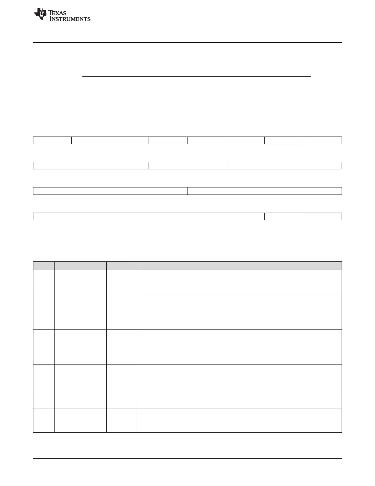
29.7.31 Input/Output Error Enable (IODFTCTRL) Register
Figure 29-60 and Table 29-48 illustrate this register. After the basic SCI/LIN module configuration, enable
the required Error mode to be created followed by IODFT Key enable.
NOTE: 1) All the bits are used in IODFT mode only.
2) Each IODFT are expected to be checked individually.
3) ISFE Error will not be Flagged during IODFT mode.
Figure 29-60. Input/Output Error Enable Register (IODFTCTRL) (offset = 90h)
31 30 29 28 27 26 25 24
BEN PBEN CEN ISFE Reserved FEN PEN BRKDT ENA
R/WL-0 R/WL-0 R/WL-0 R/WL-0 R-0 R/W-0 R/WC-0 R/WC-0
23 21 20 19 18 16
Reserved PIN SAMPLE MASK TX SHIFT
R-0 R/W-0 R/W-0
15 12 11 8
Reserved IODFTENA
R-0 R/WP-5h
7 2 1 0
Reserved LPB ENA RXP ENA
R-0 R/WP-0 R/WP-0
LEGEND: R/W = Read/Write; R = Read only; WL = Write in LIN mode only; WC = Write in SCI-compatible mode only; WP = Write in
privilege mode only; -n = value after reset
Table 29-48. Input/Output Error Enable Register (IODFTCTRL) Field Descriptions
Bit Field Value Description
31 BEN Bit error enable. This bit is effective in LIN mode only. This bit is used to create a bit error.
0 No bit error is created.
1 The bit received is ORed with 1 and passed to the bit monitor circuitry.
30 PBEN Physical bus error enable. This bit is effective in LIN mode only. This bit is used to create a
physical bus error.
0 No error is created.
1 The bit received during synch break field transmission is ORed with 1 and passed to the bit
monitor circuitry.
29 CEN Checksum error enable. This bit is effective in LIN mode only. This bit is used to create a
checksum error.
0 No error is created.
1 The polarity of the CTYPE (checksum type) in the receive checksum calculator is changed
so that a checksum error is occurred.
28 ISFE Inconsistent synch field (ISF) error enable. This bit is effective in LIN mode only. This bit is
used to create an ISF error.
0 No error is created.
1 The bit widths in the synch field are varied so that the ISF check fails and the error flag is
set.
27 Reserved 0 Reads return 0. Writes have no effect.
26 FEN Frame error enable. This bit is used to create a frame error.
0 No error is created.
1 The stop bit received is ANDed with 0 and passed to the stop bit check circuitry.

 Loading...


