www.ti.com
System and Peripheral Control Registers
175
SPNU563A–March 2018
Submit Documentation Feedback
Copyright © 2018, Texas Instruments Incorporated
Architecture
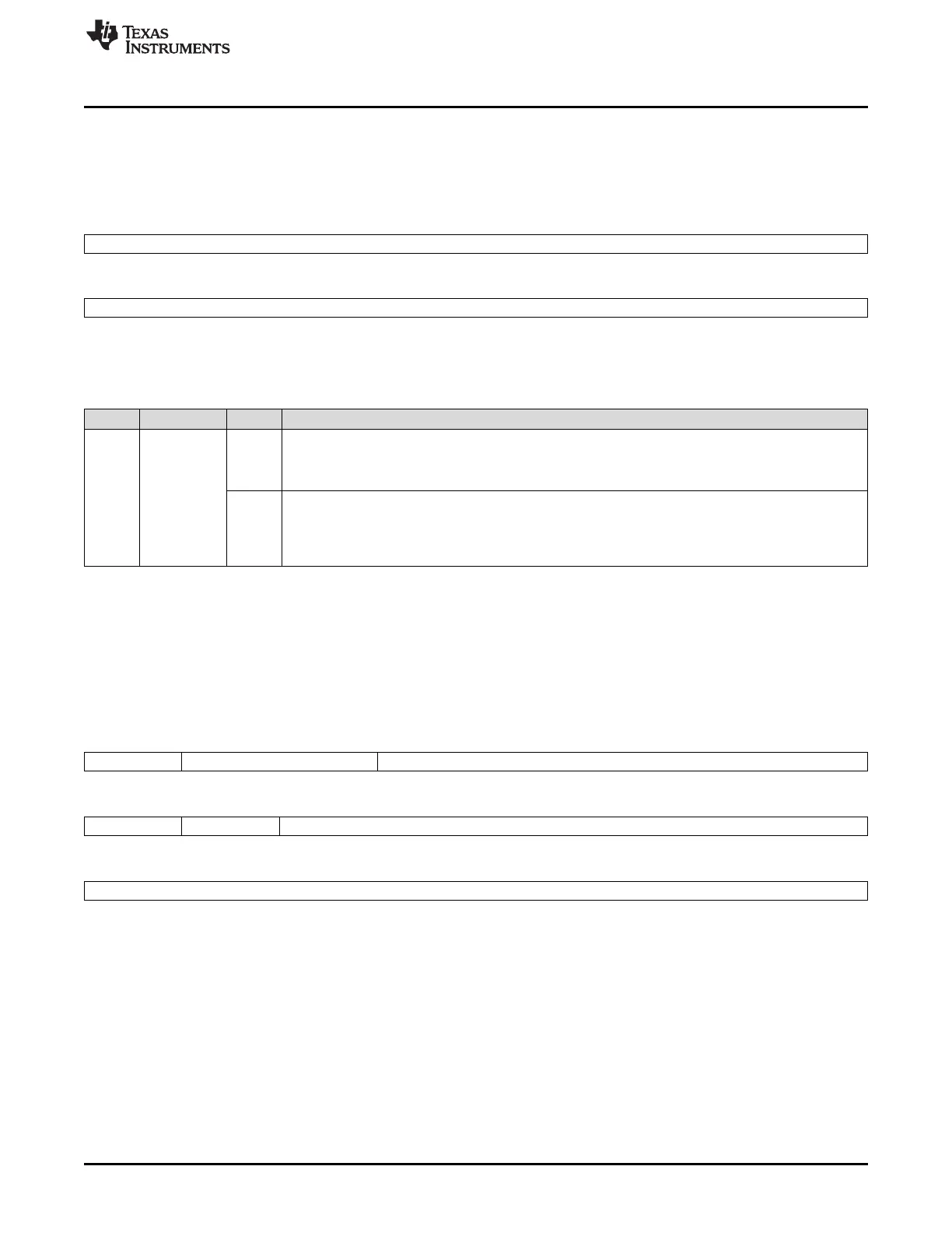
2.5.1.24 Memory Hardware Initialization Status Register (MINISTAT)
The MINISTAT register, shown in Figure 2-31 and described in Table 2-43, indicates the status of
hardware memory initialization.
Figure 2-31. Memory Hardware Initialization Status Register (MINISTAT) (offset = 6Ch)
31 16
MIDONE
R/WP-0
15 0
MIDONE
R/WP-0
LEGEND: R/W = Read/Write; WP = Write in privileged mode only; -n = value after reset
Table 2-43. Memory Hardware Initialization Status Register (MINISTAT) Field Descriptions
Bit Field Value Description
31-0 MIDONE Memory hardware initialization status bit.
0 Read: Memory module[31-0] hardware initialization is not completed.
Write: A write of 0 has no effect.
1 Read: Memory module[31-0] hardware initialization is completed.
Write: The bit is cleared to 0.
Note: Disabling the MINITGENA key (by writing from a Ah to any other value) will reset all the
individual status bits to 0.
2.5.1.25 PLL Control Register 1 (PLLCTL1)
The PLLCTL1 register, shown in Figure 2-32 and described in Table 2-44, controls the output frequency of
PLL1 (Clock Source 1 - FMzPLL). It also controls the behavior of the device if a PLL slip or oscillator
failure is detected.
Figure 2-32. PLL Control Register 1 (PLLCTL1) (offset = 70h)
31 30 29 28 24
ROS BPOS PLLDIV
R/WP-0 R/WP-1h R/WP-Fh
23 22 21 16
ROF Reserved REFCLKDIV
R/WP-0 R-0 R/WP-3h
15 0
PLLMUL
R/WP-4100h
LEGEND: R/W = Read/Write; R = Read only; WP = Write in privileged mode only; -n = value after reset

 Loading...


