÷
÷
ø
ö
ç
ç
è
æ
+
=
kFrequencyModuleCloc
dCCLKHI
HighTime
2
÷
÷
ø
ö
ç
ç
è
æ
+
=
kFrequencyModuleCloc
dCCLKLI
LowTime
2
www.ti.com
I2C Control Registers
1787
SPNU563A–March 2018
Submit Documentation Feedback
Copyright © 2018, Texas Instruments Incorporated
Inter-Integrated Circuit (I2C) Module
31.6.4 I2C Clock Divider Low Register (I2CCKL)
The I2C clock divider low register is a 16-bit memory-mapped register used to divide the master clock
down to obtain the I2C serial clock low time. Figure 31-16 and Table 31-8 describe this register.
Figure 31-16. I2C Clock Divider Low Register (I2CCKL) [offset = 0Ch]
15 0
CLKL
R/W-0
LEGEND: R/W = Read/Write; -n = value after reset
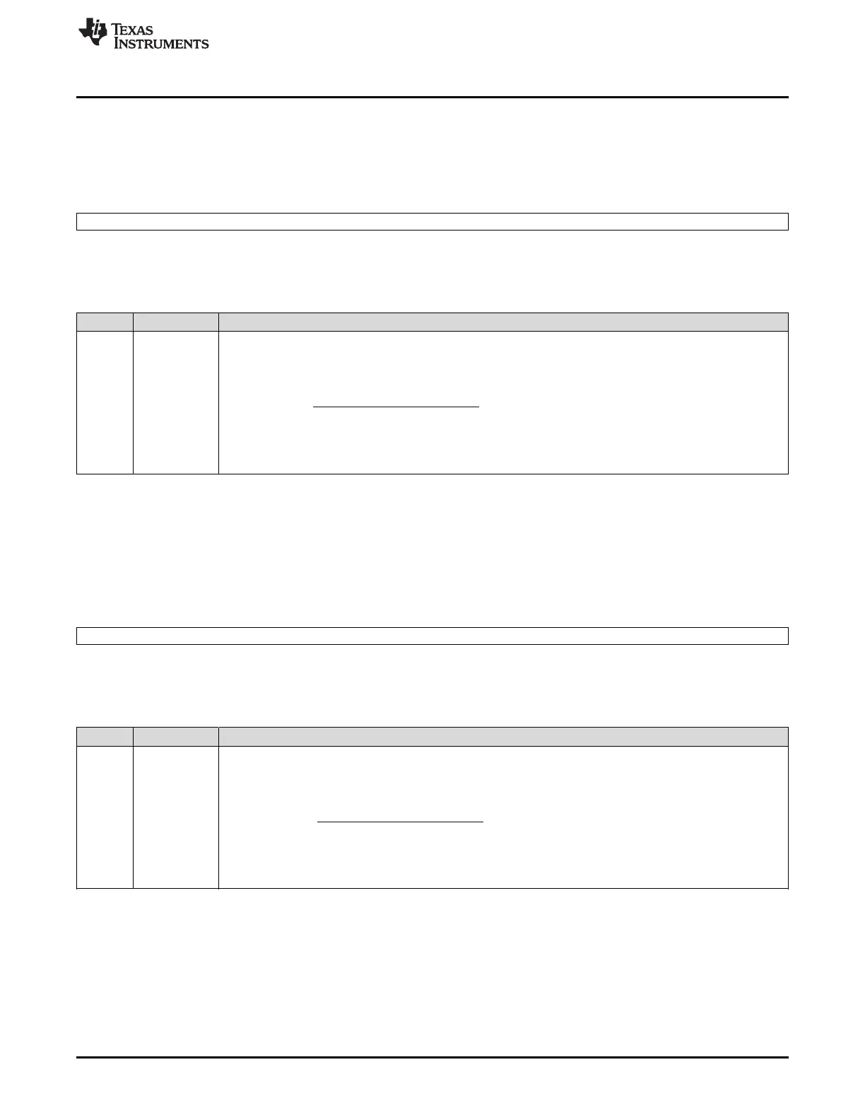
Table 31-8. I2C Clock Divider Low Register (I2CCKL) Field Descriptions
Bit Field Description
15-0 CLKL Low time clock division factor.
Used to divide down the module clock to create the low-time portion of the master clock signal that will appear
on the SCL pin:
(66)
where d is the value that depends on the I2CPSC (see Section 31.1.3).
This register must be configured while the I2C is still in reset (nIRS = 0).
31.6.5 I2C Clock Control High Register (I2CCKH)
The I2C clock divider high register is a 16-bit memory-mapped register used to divide the master clock
down to obtain the I2C serial clock high time. Figure 31-17 and Table 31-9 describe this register.
Figure 31-17. I2C Clock Control High Register (I2CCKH) [offset = 10h]
15 0
CLKH
R/W-0
LEGEND: R/W = Read/Write; -n = value after reset
Table 31-9. I2C Clock Control High Register (I2CCKH) Field Descriptions
Bit Field Description
15-0 CLKH High time clock division factor.
Used to divide down the module clock to create the high-time portion of the master clock signal that will appear
on the SCL pin:
(67)
where d is the value that depends on the I2CPSC (see Section 31.1.3).
This register must be configured while the I2C is still in reset (nIRS = 0).

 Loading...


