System and Peripheral Control Registers
www.ti.com
198
SPNU563A–March 2018
Submit Documentation Feedback
Copyright © 2018, Texas Instruments Incorporated
Architecture
2.5.1.46 System Exception Status Register (SYSESR)
The SYSESR register, shown in Figure 2-53 and described in Table 2-65, shows the source for different
resets encountered. Previous reset source status bits are not automatically cleared if new resets occur.
After reading this register, the software should clear any flags that are set so that the source of future
resets can be determined. Any bit in this register can be cleared by writing a 1 to the bit.
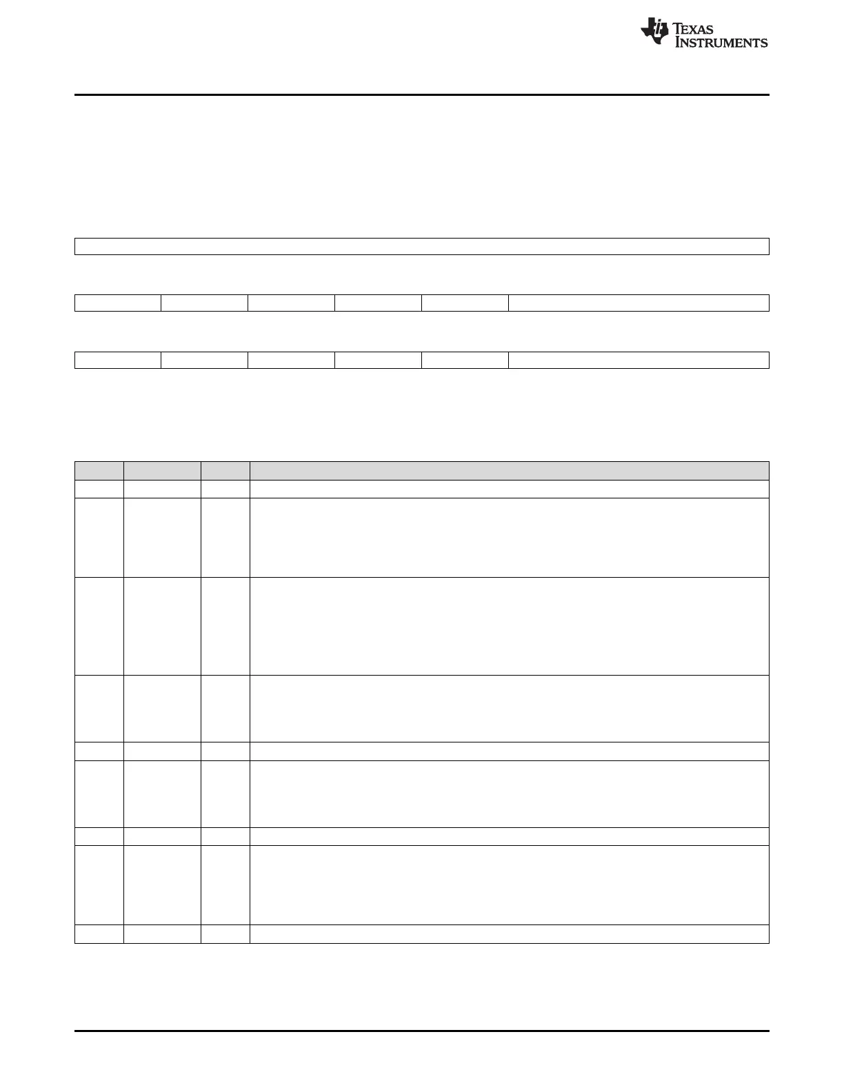
Figure 2-53. System Exception Status Register (SYSESR) (offset = E4h)
31 16
Reserved
R-0
15 14 13 12 11 10 8
PORST OSCRST WDRST Reserved DBGRST Reserved
R/WC-X R/WC-X* R/WC-X* R-0 R/WC-X* R-0
7 6 5 4 3 2 0
ICSTRST Reserved CPURST SWRST EXTRST Reserved
R/WC-X* R/WC-X* R/WC-X* R/WC-X* R/WC-X* R-0
LEGEND: R/W = Read/Write; R = Read only; C = Clear; X = value is unchanged after reset; X* = 0 after PORST but unchanged after other
resets; -n = value after reset
Table 2-65. System Exception Status Register (SYSESR) Field Descriptions
Bit Field Value Description
31-16 Reserved 0 Reads return 0. Writes have no effect.
15 PORST Power-on reset. This bit is set when a power-on reset occurs, either internally asserted by the VMON or
externally asserted by the nPORRST pin.
0 No power-on reset has occurred since this bit was last cleared.
1 A reset was caused by a power-on reset. (This bit should be cleared after being read so that
subsequent resets can be properly identified as not being power-on resets.)
14 OSCRST Reset caused by an oscillator failure or PLL cycle slip. This bit is set when a reset is caused by an
oscillator failure or PLL slip. Write 1 will clear this bit. Write 0 has no effect.
Note: The action taken when an oscillator failure or PLL slip is detected must configured in the
PLLCTL1 register.
0 No reset has occurred due to an oscillator failure or a PLL cycle slip.
1 A reset was caused by an oscillator failure or a PLL cycle slip.
13 WDRST Watchdog reset flag. This bit is set when the last reset was caused by the digital watchdog (DWD).
Write 1 will clear this bit. Write 0 has no effect.
0 No reset has occurred because of the DWD.
1 A reset was caused by the DWD.
12 Reserved 0 Reads return 0. Writes have no effect.
11 DBGRST Debug reset flag. This bit is set when the last reset was caused by the debugger reset request. Write 1
will clear this bit. Write 0 has no effect.
0 No reset has occurred because of the debugger.
1 A reset was caused by the debugger.
10-8 Reserved 0 Reads return 0. Writes have no effect.
7 ICSTRST Interconnect reset flag. This bit is set when the last CPU reset was caused by the entering and exiting
of interconnect self-test check. While the interconnect is under self-test check, the CPU is also held in
reset until the interconnect self-test is complete.
0 No CPUx reset has occurred because of an interconnect self-test check.
1 A reset has occurred to the CPUx because of the interconnect self-test check.
6 Reserved 0 Reads return 0. Writes have no effect.

 Loading...


