Digital Compare
Signals
Counter Compare
Signals
T ime Base
Signals
Dead
Band
(DB)
Counter
Compare
(CC)
Action
Qualifier
(AQ)
EPWMxA
EPWMxB
CTR = CMPB
CTR = 0
EPWMxINT
EPWMxSOCA
EPWMxSOCB
EPWMxA
EPWMxB
nTZ1 to nTZ3
CTR = CMPA
T ime-Base
(TB)
CTR = PRD
CTR = 0
CTR_Dir
EPWMxSYNCI
EPWMxSYNCO
EPWMxTZINT
PWM-
chopper
(PC)
Event
Trigger
and
Interrupt
(ET)
Trip
Zone
(TZ)
GPIO
MUX
ADC
VIM
Digital
Compare
(DC)
CPU Debug Mode
OSCFAIL or PLL SLip
Combination of EQEP1ERR
and EQEP2ERR
Digital Compare
Signals
Digital Compare
Signals
VIM
www.ti.com
ePWM Submodules
2043
SPNU563A–March 2018
Submit Documentation Feedback
Copyright © 2018, Texas Instruments Incorporated
Enhanced Pulse Width Modulator (ePWM) Module
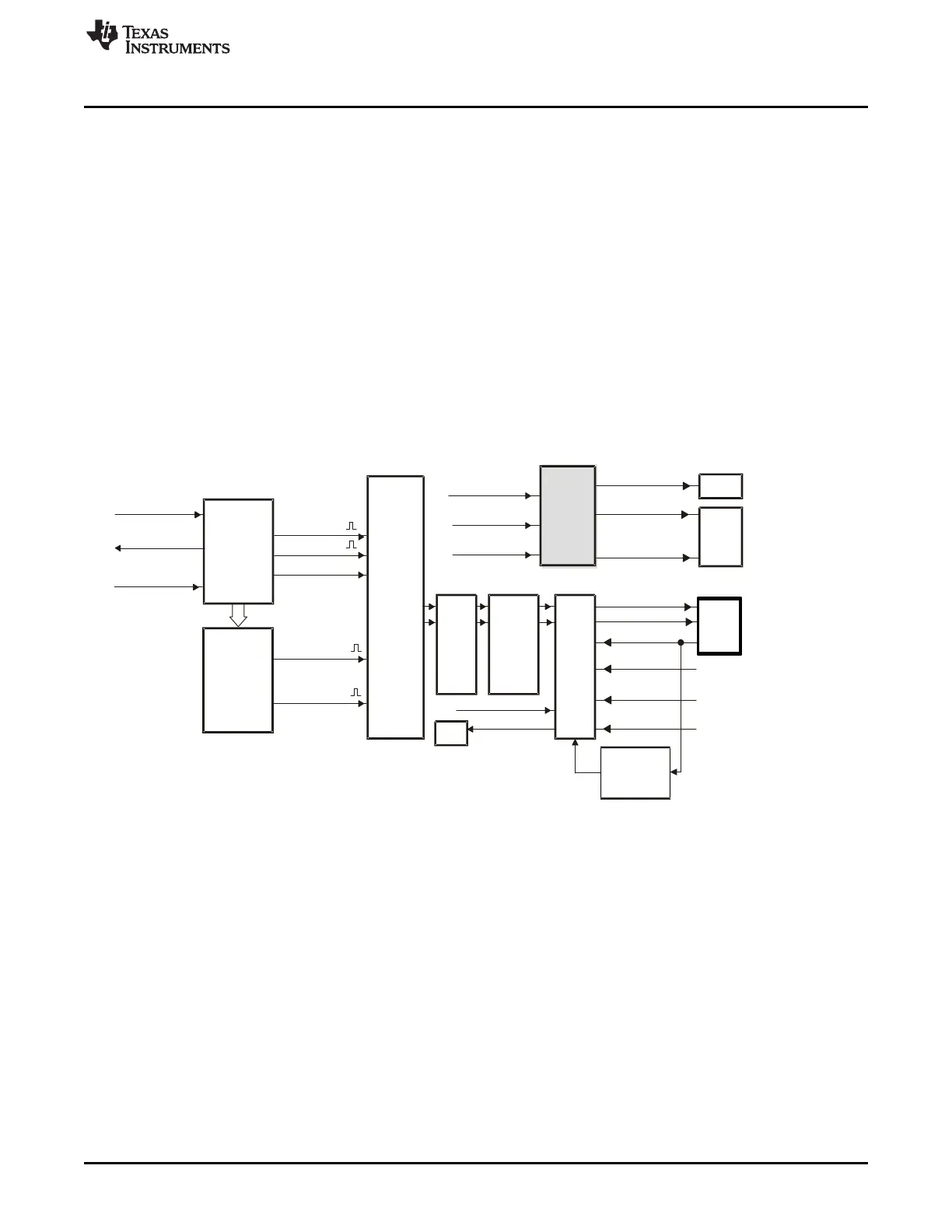
35.2.8 Event-Trigger (ET) Submodule
The key functions of the event-trigger submodule are:
• Receives event inputs generated by the time-base, counter-compare and digital-compare submodules
• Uses the time-base direction information for up/down event qualification
• Uses prescaling logic to issue interrupt requests and ADC start of conversion at:
– Every event
– Every second event
– Every third event
• Provides full visibility of event generation via event counters and flags
• Allows software forcing of Interrupts and ADC start of conversion
The event-trigger submodule manages the events generated by the time-base submodule, the counter-
compare submodule, and the digital-compare submodule to generate an interrupt to the CPU and/or a
start of conversion pulse to the ADC when a selected event occurs. Figure 35-38 illustrates where the
event-trigger submodule fits within the ePWM system.
Figure 35-38. Event-Trigger Submodule
35.2.8.1 Operational Overview of the Event-Trigger Submodule
The following sections describe the event-trigger submodule's operational highlights.
Each ePWM module has one interrupt request line connected to the VIM and two start of conversion
signals connected to the ADC module. As shown in Figure 35-39, the ePWMxSOCA and ePWMxSOCB
signals are combined to generate four special signals that can be used to trigger an ADC start of
conversion, and hence multiple modules can initiate an ADC start of conversion via the ADC trigger
inputs.

 Loading...


