www.ti.com
ePWM Registers
2083
SPNU563A–March 2018
Submit Documentation Feedback
Copyright © 2018, Texas Instruments Incorporated
Enhanced Pulse Width Modulator (ePWM) Module
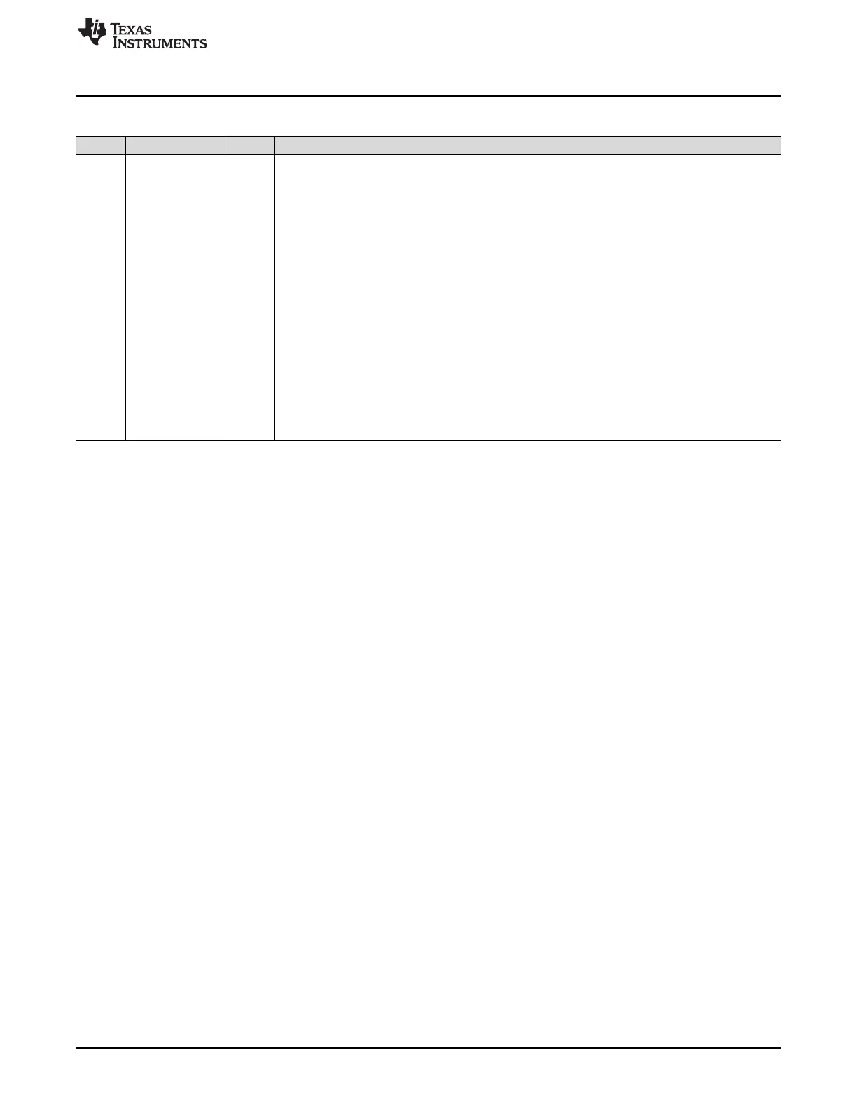
Table 35-35. Dead-Band Generator Control Register (DBCTL) Field Descriptions (continued)
Bits Name Value Description
1-0 OUT_MODE Dead-band Output Mode Control.
Bit 1 controls the S1 switch and bit 0 controls the S0 switch shown in Figure 35-28.
This allows you to selectively enable or bypass the dead-band generation for the falling-edge and
rising-edge delay.
0 Dead-band generation is bypassed for both output signals. In this mode, both the EPWMxA and
EPWMxB output signals from the action-qualifier are passed directly to the PWM-chopper
submodule.
In this mode, the POLSEL and IN_MODE bits have no effect.
1h Disable rising-edge delay. The EPWMxA signal from the action-qualifier is passed straight through
to the EPWMxA input of the PWM-chopper submodule.
The falling-edge delayed signal is seen on output EPWMxB. The input signal for the delay is
determined by DBCTL[IN_MODE].
2h The rising-edge delayed signal is seen on output EPWMxA. The input signal for the delay is
determined by DBCTL[IN_MODE].
Disable falling-edge delay. The EPWMxB signal from the action-qualifier is passed straight through
to the EPWMxB input of the PWM-chopper submodule.
3h Dead-band is fully enabled for both rising-edge delay on output EPWMxA and falling-edge delay on
output EPWMxB. The input signal for the delay is determined by DBCTL[IN_MODE].

 Loading...


