System and Peripheral Control Registers
www.ti.com
214
SPNU563A–March 2018
Submit Documentation Feedback
Copyright © 2018, Texas Instruments Incorporated
Architecture
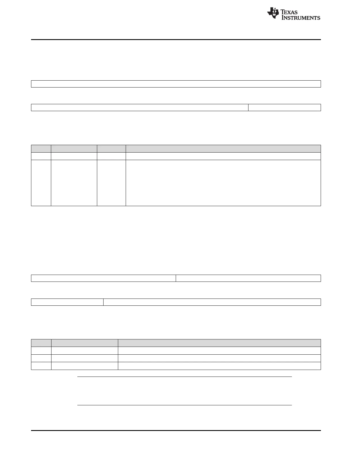
2.5.2.9 EFUSE Controller Control Register (EFC_CTLREG)
This register is shown in Figure 2-67 and described in Table 2-80.
Figure 2-67. EFUSE Controller Control Register (EFC_CTLREG) (offset = ECh)
31 16
Reserved
R-0
15 4 3 0
Reserved EFC_INSTR_WEN
R-0 R/WP-5h
LEGEND: R/W = Read/Write; R = Read only; WP = Write in privileged mode only; -n = value after reset
Table 2-80. EFUSE Controller Control Register (EFC_CTLREG) Field Descriptions
Bit Field Value Description
31-4 Reserved 0 Reads return 0. Writes have no effect.
3-0 EFC_INSTR_WEN Enable user write of 4 EFUSE controller instructions.
SYS module generates the enable signal that will be tied to OCP_FROM_WRITE_DISABLE
on efuse controller port.
Ah Writing of instructions (Program, ProgramCRA, RunAutoload, and LoadFuseScanchain) to
EFC is allowed.
Others Writing of instructions (Program, ProgramCRA, RunAutoload, and LoadFuseScanchain) in
EFC registers is blocked.
2.5.2.10 Die Identification Register Lower Word (DIEIDL_REG0)
The DIEIDL_REG0 register is a duplicate of the DIEIDL register, see Section 2.5.1.28. The DIEIDL_REG0
register, shown in Figure 2-68 and described in Table 2-81, contains information about the die wafer
number, and X, Y wafer coordinates.
Figure 2-68. Die Identification Register, Lower Word (DIEIDL_REG0) [offset = F0h]
31 24 23 16
WAFER # Y WAFER COORDINATE
R-D R-D
15 12 11 0
Y WAFER COORDINATE X WAFER COORDINATE
R-D R-D
LEGEND: R = Read only; D = value is device specific; -n = value after reset
Table 2-81. Die Identification Register, Lower Word (DIEIDL_REG0) Field Descriptions
Bit Field Description
31-24 WAFER # These read-only bits contain the wafer number of the device.
23-12 Y WAFER COORDINATE These read-only bits contain the Y wafer coordinate of the device.
11-0 X WAFER COORDINATE These read-only bits contain the X wafer coordinate of the device.
NOTE: Die Identification Information
The die identification information will vary from unit to unit. This information is programmed
by TI as part of the initial device test procedure.

 Loading...


