ADIN31
ADIN0
On-chipInput “Multiplexer”
External 8:1 Analog Multiplexers
to ADCSample/HoldCircuit
012293031
ADGxSEL
1 00 0 0 1
0
1
29
30
31
Index
External,5-bit
Internal,5-bit
ChannelIdentifiers
7 30
5 1
0 29
4 2
1 1
8:1
8:1
8:1
8:1
LUT index, 0to31
5-bitSelect forext.channelmux
InternalChannel
Select,32bits
Current
MaxCount
Count
4 2
1 1
3
2
EnableStrobe
Generator
1-bit EnableornEnable
forext.channelmux
StartOf
Conversion
Incrementon
EndofConversion
Resetwhen
CurrentCount=MaxCount
www.ti.com
Basic Operation
863
SPNU563A–March 2018
Submit Documentation Feedback
Copyright © 2018, Texas Instruments Incorporated
Analog To Digital Converter (ADC) Module
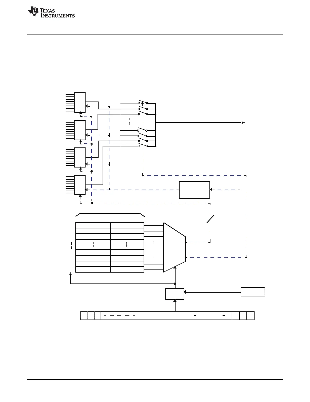
22.2.2.2.2.2 Example ADC Conversion Sequence Using Enhanced Channel Selection Mode
Consider the example conversion Group1 configuration shown in Figure 22-12. Only bits 0 and 31 of
ADG1SEL are set. Assume that all other bits in this register are zeros.
In case of the default sequential channel selection mode, the write to the ADG1SEL register would cause
the Group1 conversions to start with channel 0 followed by channel 31. The conversions would then stop
or repeat in this order depending on whether Group1 is in single or continuous conversion mode.
Figure 22-12. Group1 Enhanced Channel Selection Mode Example

 Loading...


