GPIO Functionality
www.ti.com
1666
SPNU563A–March 2018
Submit Documentation Feedback
Copyright © 2018, Texas Instruments Incorporated
Serial Communication Interface (SCI)/ Local Interconnect Network (LIN)
Module
29.6.3 Out of Reset
The following apply if the device is out of reset:
• Pull control. The pull control is enabled by clearing the PD (pull control disable) bit in the SCIPIO7
register (Section 29.7.21). In this case, if the PSL (pull select) bit in the SCIPIO8 register
(Section 29.7.22) is set, the pin will have a pull-up. If the PSL bit is cleared, the pin will have a pull-
down. If the PD bit is set in the control register, there is no pull-up or pull-down on the pin.
• Input buffer. The input buffer is permanently enabled in this device.
NOTE: The pull-disable logic depends on the pin direction. It is independent of whether the device is
in I/O or functional mode. If the pin is configured as output or transmit, then the pulls are
disabled automatically.
• Output buffer. A pin can be driven as an output pin if the TX DIR bit is set in the pin direction control
register (SCIPIO1; Section 29.7.15) AND the open-drain feature is not enabled in the SCIPIO6 register
(Section 29.7.20).
29.6.4 Open-Drain Feature Enabled on a Pin
The following apply if the open-drain feature is enabled on a pin:
• The output buffer is enabled if a low signal is being driven on to the pin.
• The output buffer is disabled (the direction control signal DIR is internally forced low) if a high signal is
being driven on to the pin.
NOTE: The open-drain feature is available only in I/O mode (SCIPIO0; Section 29.7.14).
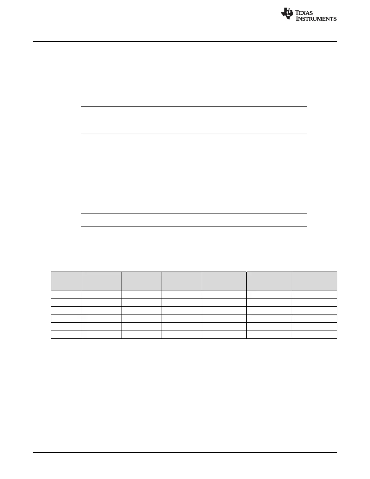
29.6.5 Summary
The behavior of the input buffer, output buffer, and the pull control is summarized in Table 29-9.
(1)
X = Don’t care
(2)
DIR = 0 for input, = 1 for output
(3)
PULDIS = 0 for enabling pull control, = 1 for disabling pull control
(4)
PULSEL= 0 for pull-down functionality, = 1 for pull-up functionality
Table 29-9. Input Buffer, Output Buffer, and Pull Control Behavior as GPIO Pins
(1)
Device
under
Reset?
Pin Direction
(DIR)
(2)
Pull Disable
(PULDIS)
(3)
Pull Select
(PULSEL)
(4)
Pull Control Output Buffer Input Buffer
Yes X X X Enabled Disabled Enabled
No 0 0 0 Pull down Disabled Enabled
No 0 0 1 Pull up Disabled Enabled
No 0 1 0 Disabled Disabled Enabled
No 0 1 1 Disabled Disabled Enabled
No 1 X X Disabled Enabled Enabled

 Loading...


