www.ti.com
PSC Registers
161
SPRUH91D–March 2013–Revised September 2016
Submit Documentation Feedback
Copyright © 2013–2016, Texas Instruments Incorporated
Power and Sleep Controller (PSC)
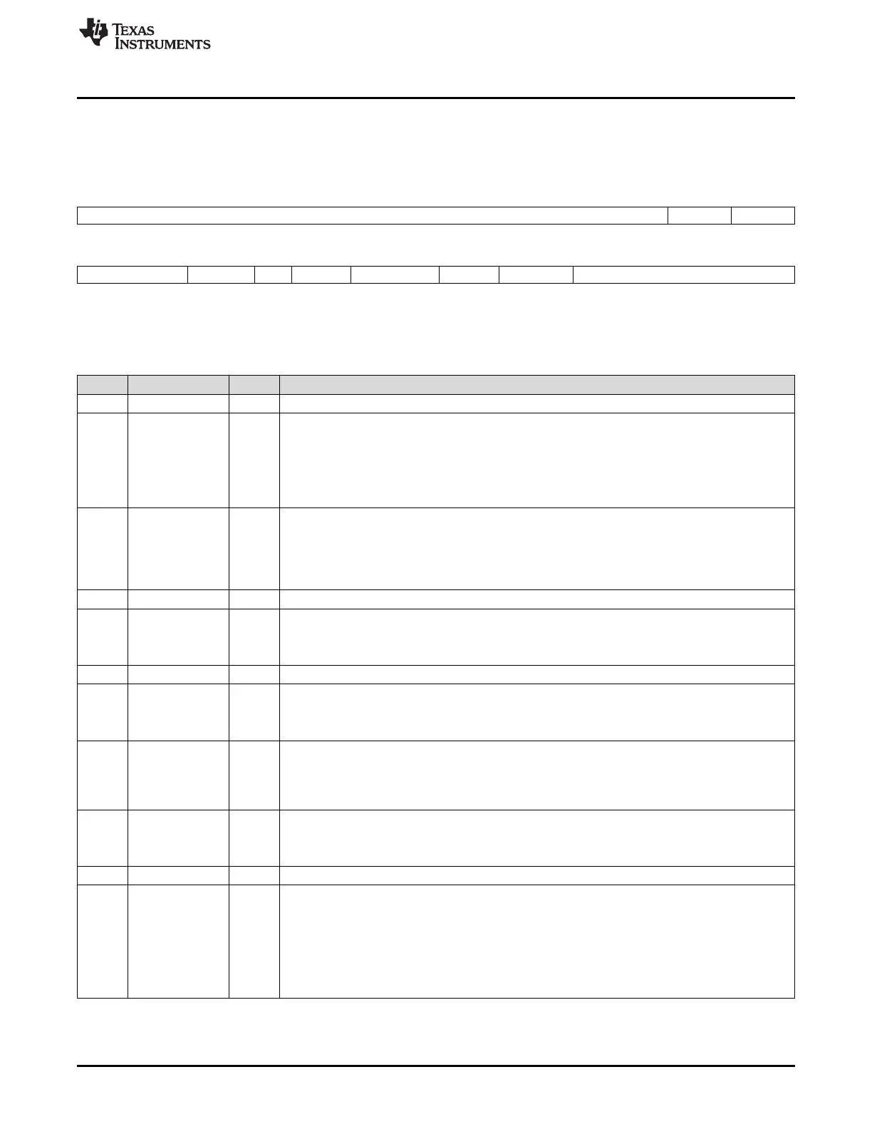
8.6.17 Module Status n Register (MDSTATn)
The module status n register (MDSTATn) is shown in Figure 8-17 and described in Table 8-22.
Figure 8-17. Module Status n Register (MDSTATn)
31 18 17 16
Reserved EMUIHB EMURST
R-0 R-0 R-0
15 13 12 11 10 9 8 7 6 5 0
Reserved MCKOUT Rsvd MRST LRSTDONE LRST Reserved STATE
R-0 R-0 R-1 R-0 R-1 R-1 R-0 R-0
LEGEND: R = Read only; -n = value after reset
Table 8-22. Module Status n Register (MDSTATn) Field Descriptions
Bit Field Value Description
31-18 Reserved 0 Reserved
17 EMUIHB Emulation alters module state. This bit applies to DSP module (module 15). This field is 0 for all
other modules.
0 No emulation altering user-desired module state programmed in the NEXT bit in the module control
15 register (MDCTL15).
1 Emulation altered user-desired state programmed in the NEXT bit in MDCTL15. If you desire to
generate a PSCINT upon this event, you must set the EMUIHBIE bit in MDCTL15.
16 EMURST Emulation alters module reset. This bit applies to DSP module (module 15). This field is 0 for all
other modules.
0 No emulation altering user-desired module reset state.
1 Emulation altered user-desired module reset state. If you desire to generate a PSCINT upon this
event, you must set the EMURSTIE bit in the module control 15 register (MDCTL15).
15-13 Reserved 0 Reserved
12 MCKOUT Module clock output status. Shows status of module clock.
0 Module clock is off.
1 Module clock is on.
11 Reserved 1 Reserved
10 MRST Module reset status. Reflects actual state of module reset.
0 Module reset is asserted.
1 Module reset is de-asserted.
9 LRSTDONE Local reset done. Software is responsible for checking if local reset is done before accessing this
module. This bit applies to DSP module (module 15). This field is 1 for all other modules.
0 Local reset is not done.
1 Local reset is done.
8 LRST Module local reset status. This bit applies to DSP module (module 15).
0 Local reset is asserted.
1 Local reset is de-asserted.
7-6 Reserved 0 Reserved
5-0 STATE 0-3Fh Module state status: indicates current module status.
0 SwRstDisable state
1h SyncReset state
2h Disable state
3h Enable state
4h-3Fh Indicates transition