Example Configuration
www.ti.com
740
SPRUH91D–March 2013–Revised September 2016
Submit Documentation Feedback
Copyright © 2013–2016, Texas Instruments Incorporated
External Memory Interface A (EMIFA)
18.3.2.1.5 SDRAM Configuration Register (SDCR) Settings for the EMIFA to K4S641632H-TC(L)70
Interface
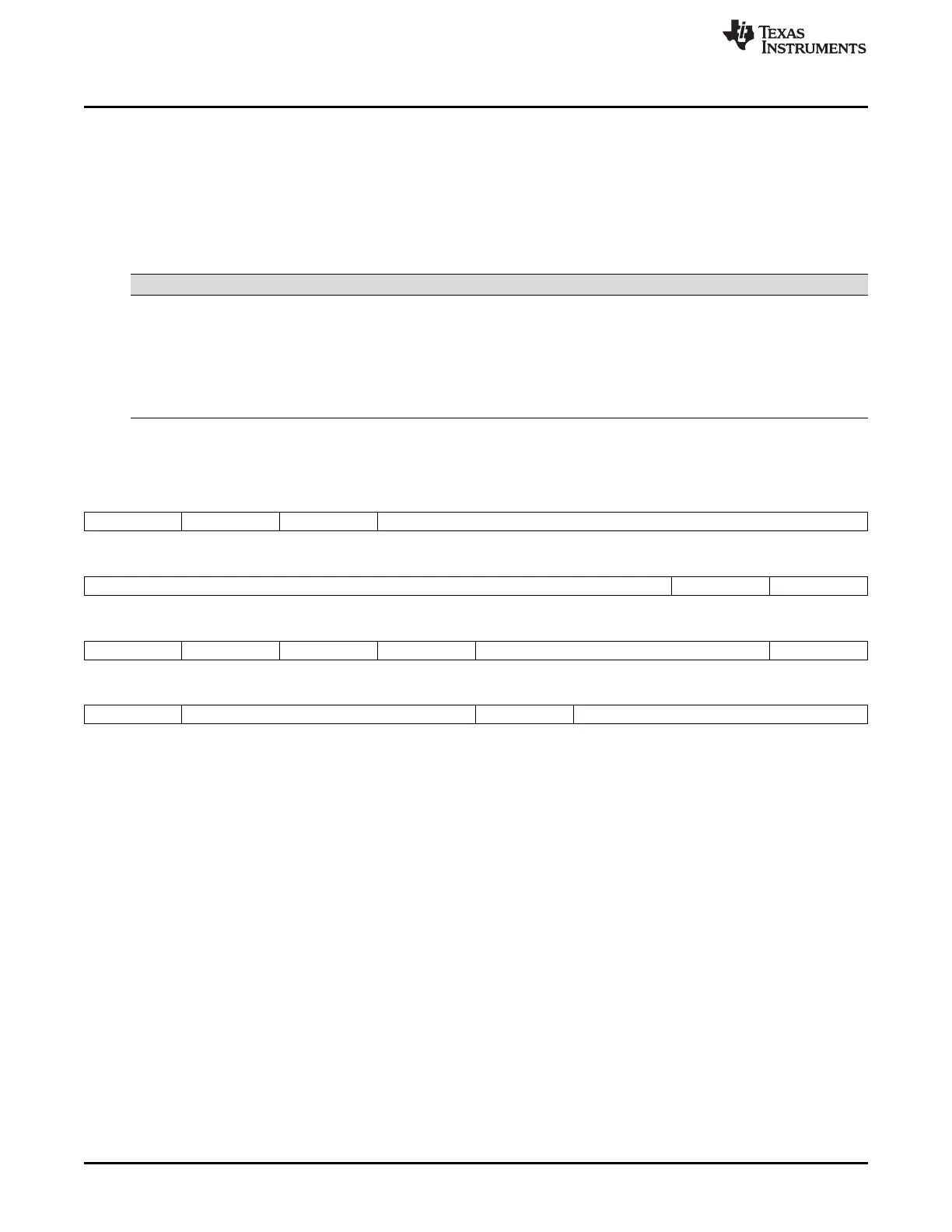
Finally, the fields of the SDRAM configuration register (SDCR) should be programmed as described in
Table 18-30 to properly interface with the K4S641632H-TC(L)70 device. Based on these settings, a value
of 4720h should be written to SDCR. Figure 18-22 shows how SDCR should be programmed. The EMIFA
is now ready to perform read and write accesses to the SDRAM.
Table 18-30. SDCR Field Values For the EMIFA to K4S641632H-TC(L)70 Interface
Field Value Purpose
SR 0 To avoid placing the EMIFA into the self refresh state
NM 1 To configure the EMIFA for a 16-bit data bus
CL 011b To select a CAS latency of 3
BIT11_9LOCK 1 To allow the CL field to be written
IBANK 010b To select 4 internal SDRAM banks
PAGESIZE 0 To select a page size of 256 words
Figure 18-22. SDRAM Configuration Register (SDCR)
31 30 29 28 24
0 0 0 0 0000
SR Reserved Reserved Reserved
23 18 17 16
00 0000 0 0
Reserved Reserved Reserved
15 14 13 12 11 9 8
0 1 0 0 011 1
Reserved NM Reserved Reserved CL BIT11_9LOCK
7 6 4 3 2 0
0 010 0 000
Reserved IBANK Reserved PAGESIZE

 Loading...


