S Slave address R/W ACK Data ACK Data ACK P
7 n n
1 1 1 1 1 1
I2Cx_SDA
I2Cx_SCL
MSB
Acknowledgement
bit from slave
(No-)Acknowledgement
bit from receiver
1 2 7 8 9 1 2 8 9
Slave address
ACK
START
condition (S)
STOP
condition (P)
R/W ACK
Data
www.ti.com
Architecture
897
SPRUH91D–March 2013–Revised September 2016
Submit Documentation Feedback
Copyright © 2013–2016, Texas Instruments Incorporated
Inter-Integrated Circuit (I2C) Module
22.2.6 Serial Data Formats
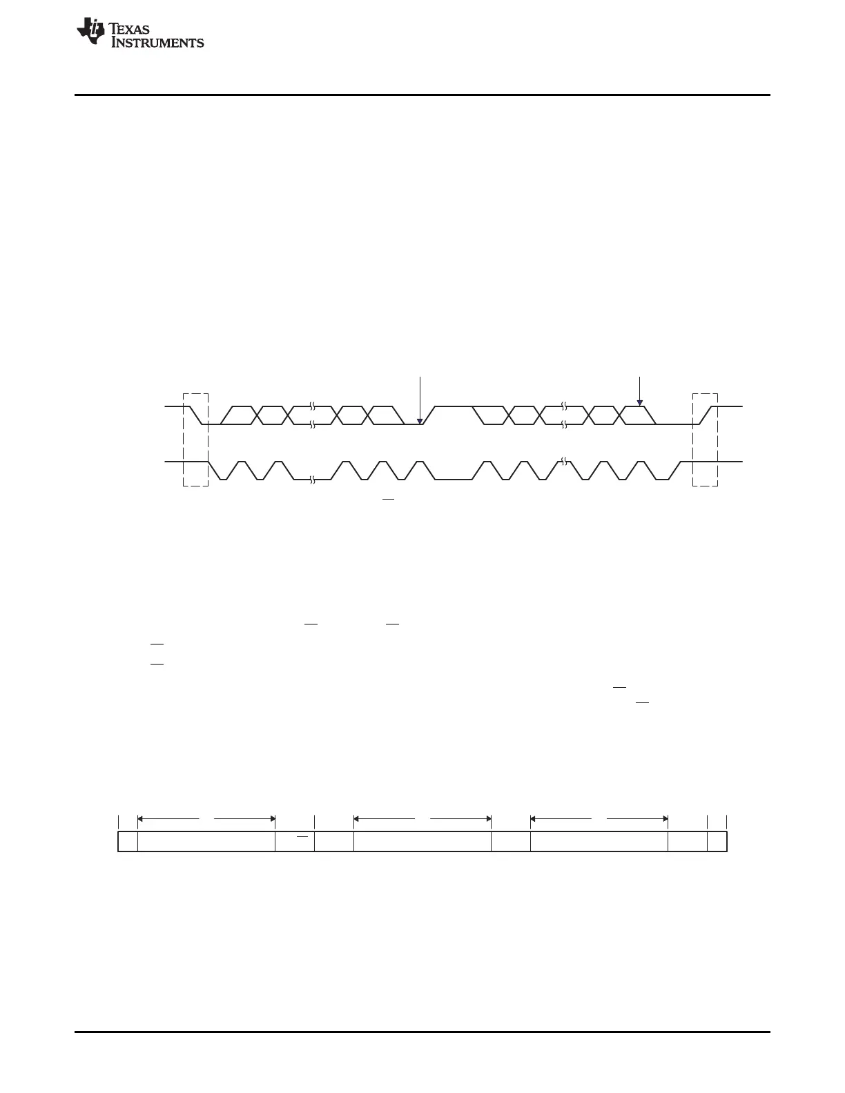
Figure 22-7 shows an example of a data transfer on the I2C-bus. The I2C peripheral supports 1-bit to 8-bit
data values. Figure 22-7 is shown in an 8-bit data format (BC = 000 in ICMDR). Each bit put on the
I2Cx_SDA line is equivalent to one pulse on the I2Cx_SCL line. The data is always transferred with the
most-significant bit (MSB) first. The number of data values that can be transmitted or received is
unrestricted; however, the transmitters and receivers must agree on the number of data values being
transferred.
The I2C peripheral supports the following data formats:
• 7-bit addressing mode
• 10-bit addressing mode
• Free data format mode
Figure 22-7. I2C Peripheral Data Transfer
22.2.6.1 7-Bit Addressing Format
In the 7-bit addressing format (Figure 22-8), the first byte after a START condition (S) consists of a 7-bit
slave address followed by a R/W bit. The R/W bit determines the direction of the data.
• R/W = 0: The master writes (transmits) data to the addressed slave.
• R/W = 1: The master reads (receives) data from the slave.
An extra clock cycle dedicated for acknowledgment (ACK) is inserted after the R/W bit. If the slave inserts
the ACK bit, n bits of data from the transmitter (master or slave, depending on the R/W bit) follow it. n is a
number from 1 to 8 that the bit count (BC) bits of ICMDR determine. The receiver inserts an ACK bit after
the data bits have been transferred.
Write a 0 to the expanded address enable (XA) bit of ICMDR to select the 7-bit addressing format.
Figure 22-8. I2C Peripheral 7-Bit Addressing Format (FDF = 0, XA = 0 in ICMDR)
n = The number of data bits (from 1 to 8) specified by the bit count (BC) field of ICM DR.