Registers
www.ti.com
764
SPRUH91D–March 2013–Revised September 2016
Submit Documentation Feedback
Copyright © 2013–2016, Texas Instruments Incorporated
External Memory Interface A (EMIFA)
18.4.5 Asynchronous n Configuration Registers (CE2CFG-CE5CFG)
The asynchronous n configuration registers (CE2CFG, CE3CFG, CE4CFG, and CE5CFG) are used to
configure the shaping of the address and control signals during an access to asynchronous memory
connected to CS2, CS3, CS4, and CS5, respectively. It is also used to program the width of asynchronous
interface and to select from various modes of operation. This register can be written prior to any transfer,
and any asynchronous transfer following the write will use the new configuration. The CEnCFG is shown
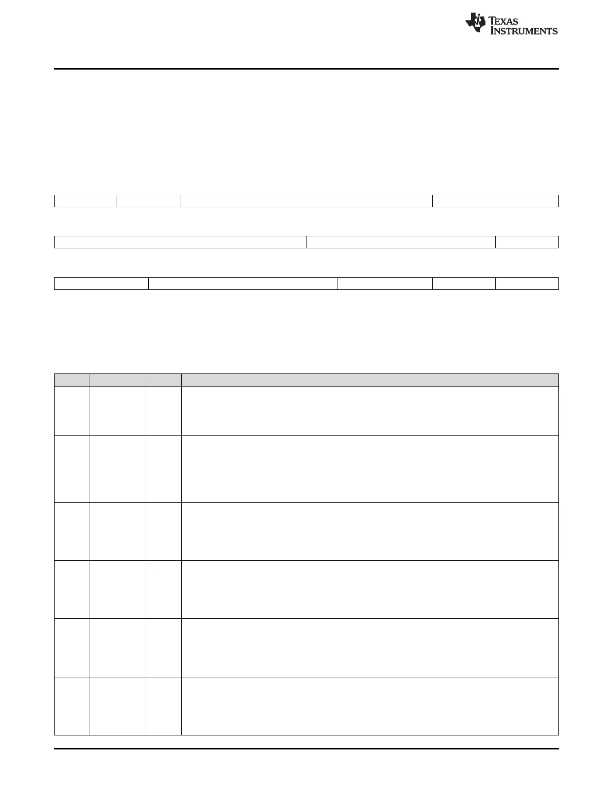
in Figure 18-35 and described in Table 18-53.
Figure 18-35. Asynchronous n Configuration Register (CEnCFG)
31 30 29 26 25 24
SS EW
(A)
W_SETUP W_STROBE
(B)
R/W-0 R/W-0 R/W-Fh R/W-3Fh
23 20 19 17 16
W_STROBE
(B)
W_HOLD R_SETUP
R/W-3Fh R/W-7h R/W-Fh
15 13 12 7 6 4 3 2 1 0
R_SETUP R_STROBE
(B)
R_HOLD TA ASIZE
R/W-Fh R/W-3Fh R/W-7h R/W-3h R/W-0
LEGEND: R/W = Read/Write; R = Read only; -n = value after reset
A. The EW bit must be cleared to 0 when operating in NAND Flash mode.
B. This bit field must be cleared to 0 if the EMIFA on your device does not have an EMA_WAIT pin.
Table 18-53. Asynchronous n Configuration Register (CEnCFG) Field Descriptions
Bit Field Value Description
31 SS Select Strobe bit. This bit defines whether the asynchronous interface operates in Normal Mode or
Select Strobe Mode. See Section 18.2.5 for details on the two modes of operation.
0 Normal Mode enabled.
1 Select Strobe Mode enabled.
30 EW Extend Wait bit. This bit defines whether extended wait cycles will be enabled. See Section 18.2.5.7 on
extended wait cycles for details. This bit field must be cleared to 0, if the EMIFA on your device does
not have an EMA_WAIT pin. The CSn_WAIT bit in the asynchronous wait cycle configuration register
(AWCC) must also be configured to determine which EMA_WAIT pin is used for memory accesses.
0 Extended wait cycles disabled.
1 Extended wait cycles enabled.
29-26 W_SETUP 0-Fh Write setup width in the format n - 1, where n = number of EMA_CLK cycles. See Section 18.2.5.3 for
details.
0h = Divide-by-1
1h = Divide-by-2
…
2h – Fh = Divide-by-3 to Divide-by-16
25-20 W_STROBE 0-3Fh Write strobe width in the format n - 1, where n = number of EMA_CLK cycles. See Section 18.2.5.3 for
details.
0h = Divide-by-1
1h = Divide-by-2
…
2h – 3Fh = Divide-by-3 to Divide-by-64
19-17 W_HOLD 0-7h Write hold width in the format n - 1, where n = number of EMA_CLK cycles. See Section 18.2.5.3 for
details.
0h = Divide-by-1
1h = Divide-by-2
…
2h – 7h = Divide-by-3 to Divide-by-8
16-13 R_SETUP 0-Fh Read setup width in the format n - 1, where n = number of EMA_CLK cycles. See Section 18.2.5.3 for
details.
0h = Divide-by-1
1h = Divide-by-2
…
2h – 1Fh = Divide-by-3 to Divide-by-16