TBCNT
EPWMxA
EPWMxB
TBPRD
(value)
CB
CAP
P P
P
CB
CA
P
P
Architecture
www.ti.com
314
SPRUH91D–March 2013–Revised September 2016
Submit Documentation Feedback
Copyright © 2013–2016, Texas Instruments Incorporated
Enhanced High-Resolution Pulse-Width Modulator (eHRPWM)
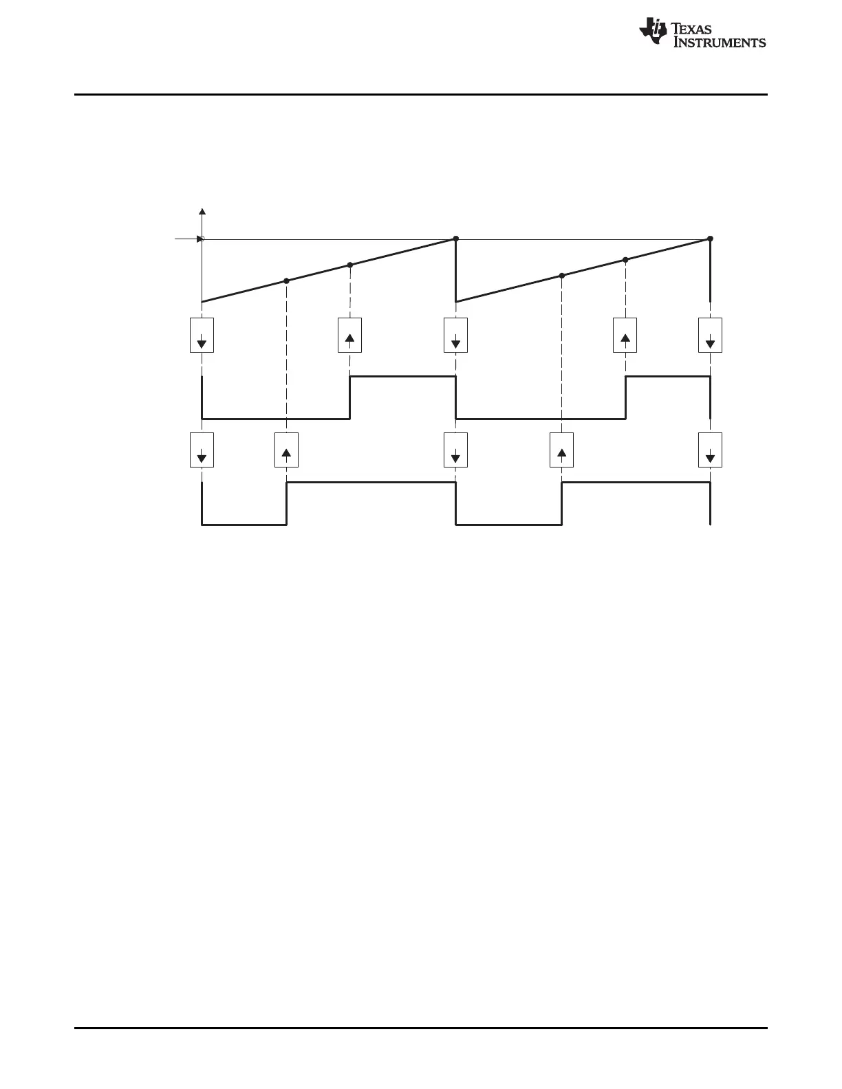
Table 14-15 and Table 14-16 contains initialization and runtime register configurations for the waveforms
in Figure 14-23.
Figure 14-23. Up, Single Edge Asymmetric Waveform With Independent Modulation on EPWMxA and
EPWMxB—Active Low
(1) PWM period = (TBPRD + 1 ) × T
TBCLK
(2) Duty modulation for EPWMxA is set by CMPA, and is active low (that is, the low time duty is proportional to
CMPA).
(3) Duty modulation for EPWMxB is set by CMPB and is active low (that is, the low time duty is proportional to
CMPB).
(4) The Do Nothing actions ( X ) are shown for completeness here, but will not be shown on subsequent
diagrams.
(5) Actions at zero and period, although appearing to occur concurrently, are actually separated by one TBCLK
period. TBCNT wraps from period to 0000h.

 Loading...


