www.ti.com
Registers
973
SPRUH91D–March 2013–Revised September 2016
Submit Documentation Feedback
Copyright © 2013–2016, Texas Instruments Incorporated
Liquid Crystal Display Controller (LCDC)
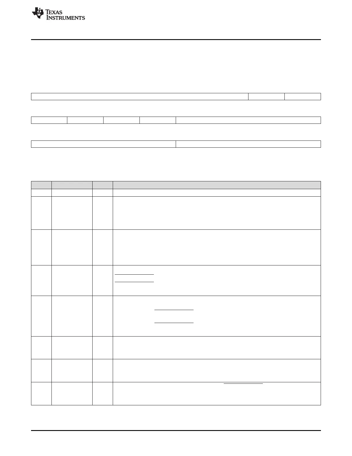
23.3.11 LCD Raster Timing Register 2 (RASTER_TIMING_2)
LCD raster timing 2 register (RASTER_TIMING_2) contains bit-fields that are used to control various
functions associated with the timing of the LCD controller. The RASTER_TIMING_2 is shown in
Figure 23-35 and described in Table 23-22.
Figure 23-35. LCD Raster Timing Register 2 (RASTER_TIMING_2)
31 26 25 24
Reserved SYNC_CTRL SYNC_EDGE
R-0 R/W-0 R/W-0
23 22 21 20 19 16
BIAS IPC IHS IVS ACB_I
R/W-0 R/W-0 R/W-0 R/W-0 R/W-0
15 8 7 0
ACB Reserved
R/W-0 R-0
LEGEND: R/W = Read/Write; R = Read only; -n = value after reset
Table 23-22. LCD Raster Timing Register 2 (RASTER_TIMING_2) Field Descriptions
Bit Field Value Description
31-26 Reserved 0 Reserved
25 SYNC_CTRL Horizontal and Vertical Sync Control
0 Inactive. SYNC_EDGE is ignored and the activation and deactivation of LCD_HSYNC and
LCD_VSYNC will be defined by bit 22 below.
1 Active. Allow SYNC_EDGE to define the LCD_PCLK edge (rising or falling) used to activate and
deactivate LCD_HSYNC and LCD_VSYNC.
24 SYNC_EDGE Horizontal and Vertical Sync Edge. The activation and deactivation of LCD_HSYNC and
LCD_VSYNC will occur on the defined LCD_PCLK edge.
0 Rising edge.
1 Falling edge.
SYNC_CTRL must be active in order to use this bit.
23 BIAS Invert AC Bias
0 LCD_AC_ENB_CS is an active-high pulse.
1 LCD_AC_ENB_CS is an active-low pulse.
In STN mode, the activation of this bit is ignored.
22 IPC Invert Pixel Clock
0 LCD Data (LCD_D[15:0]) is driven on the rising edge of LCD_PCLK, while LCD_VSYNC,
LCD_HSYNC, and LCD_AC_ENB_CS are driven on the falling edge.
1 LCD Data (LCD_D[15:0]) is driven on the falling edge of LCD_PCLK, while LCD_VSYNC,
LCD_HSYNC, and LCD_AC_ENB_CS are driven on the rising edge.
LCD_VSYNC and LCD_HSYNC may be altered as defined by bits 24 and 25 above.
21 IHS Invert Line Clock
0 LCD_HSYNC is an active high pulse.
1 LCD_HSYNC is an active low pulse.
20 IVS Invert Frame Clock
0 LCD_VSYNC is an active high pulse.
1 LCD_VSYNC is an active low pulse.
19-16 ACB_I 0-Fh This value is used to specify the number of AC Bias (LCD_AC_ENB_CS) output transition counts
before setting the AC bias interrupt bit in register LCD_STAT. This counter is stopped when the
interrupt is set and remains stopped until the AC bias interrupt status is cleared. A value of zero will
not produce an interrupt.