www.ti.com
MPU Registers
97
SPRUH91D–March 2013–Revised September 2016
Submit Documentation Feedback
Copyright © 2013–2016, Texas Instruments Incorporated
Memory Protection Unit (MPU)
5.3.10 Programmable Range n Start Address Registers (PROGn_MPSAR)
NOTE: In some cases the amount of physical memory in actual use may be less than the maximum
amount of memory supported by the device. For example, the device may support a total of
512 Mbytes of SDRAM memory, but your design may only populate 128 Mbytes. In such
cases, the unpopulated memory range must be protected in order to prevent
unintended/disallowed aliased access to protected memory, especially memory. One of the
programmable address ranges could be used to detect accesses to this unpopulated
memory.
The programmable range n start address register (PROGn_MPSAR) holds the start address for the range
n. The PROGn_MPSAR is writeable by a supervisor entity only.
The start address must be aligned on a page boundary. The size of the page depends on the MPU: the
page size for MPU1 is 1 kBbyte; the page size for MPU2 is 64 kBytes. The size of the page determines
the width of the address field in PROGn_MPSAR and the programmable range n end address register
(PROGn_MPEAR). For example, to protect a 64-kB page starting at byte address 8001 0000h, write
8001 0000h to PROGn_MPSAR and 8001 FFFFh to PROGn_MPEAR.
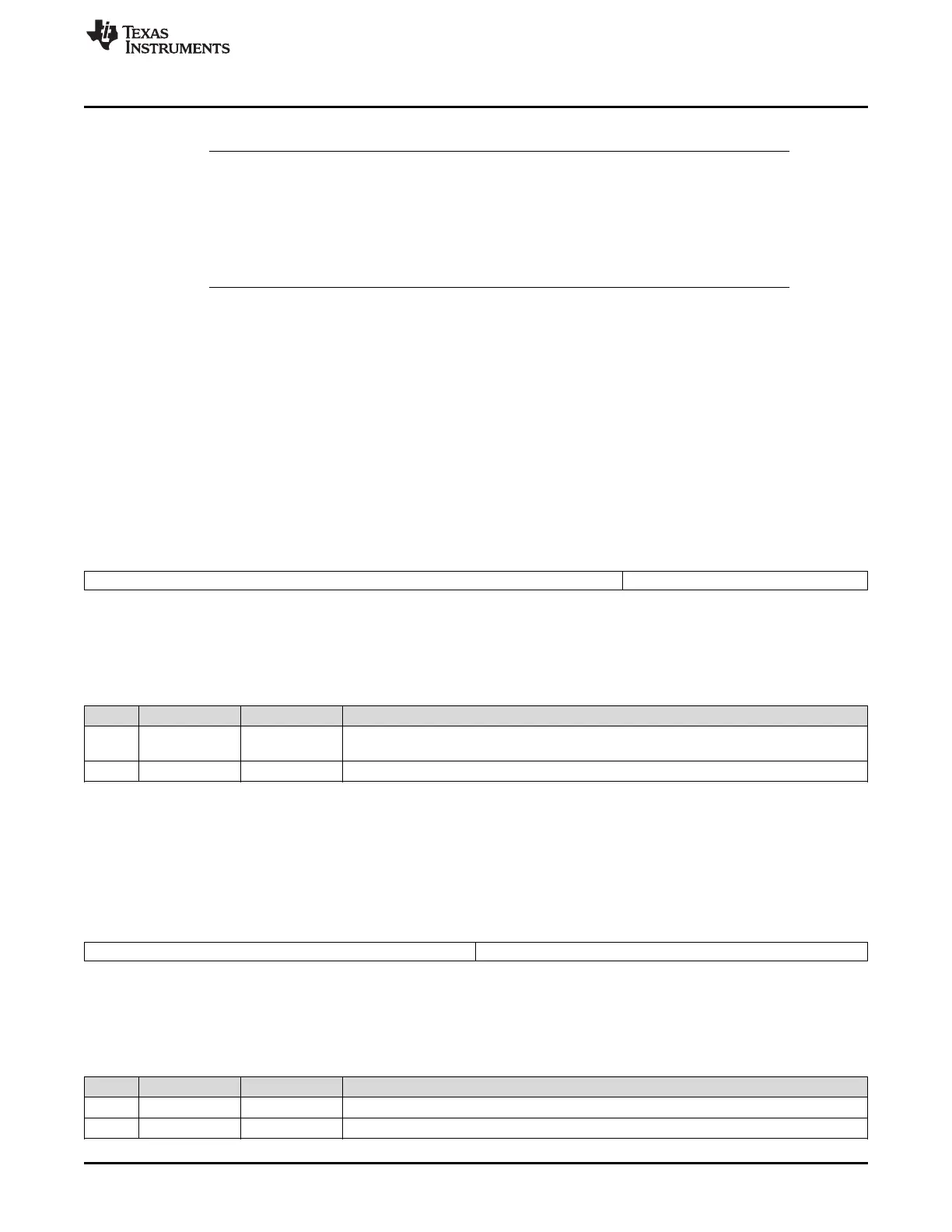
5.3.10.1 MPU1 Programmable Range n Start Address Register (PROG1_MPSAR-PROG6_MPSAR)
The PROGn_MPSAR for MPU1 is shown in Figure 5-12 and described in Table 5-15.
Figure 5-12. MPU1 Programmable Range n Start Address Register (PROGn_MPSAR)
31 10 9 0
START_ADDR Reserved
R/W-20 0000h R-0
LEGEND: R/W = Read/Write; R = Read only; -n = value after reset
Table 5-15. MPU1 Programmable Range n Start Address Register (PROGn_MPSAR)
Field Descriptions
Bit Field Value Description
31-10 START_ADDR 20 0000h–
20 007Fh
Start address for range N.
9-0 Reserved 0 Reserved
5.3.10.2 MPU2 Programmable Range n Start Address Register (PROG1_MPSAR-PROG12_MPSAR)
The PROGn_MPSAR for MPU2 is shown in Figure 5-13 and described in Table 5-16.
Figure 5-13. MPU2 Programmable Range n Start Address Register (PROGn_MPSAR)
31 16 15 0
START_ADDR Reserved
R/W-C000h R-0
LEGEND: R/W = Read/Write; R = Read only; -n = value after reset
Table 5-16. MPU2 Programmable Range n Start Address Register (PROGn_MPSAR)
Field Descriptions
Bit Field Value Description
31-16 START_ADDR C000h–DFFFh Start address for range N.
15-0 Reserved 0 Reserved