Registers
www.ti.com
378
SPRUH91D–March 2013–Revised September 2016
Submit Documentation Feedback
Copyright © 2013–2016, Texas Instruments Incorporated
Enhanced High-Resolution Pulse-Width Modulator (eHRPWM)
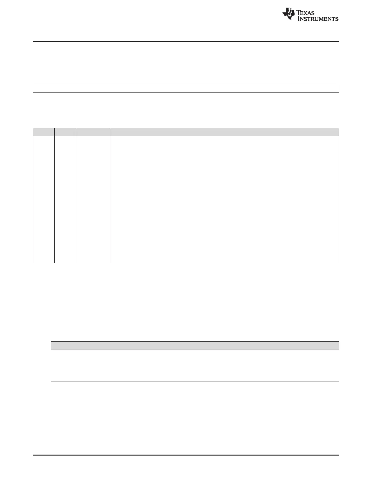
14.4.2.3 Counter-Compare B Register (CMPB)
The counter-compare B register (CMPB) is shown in Figure 14-72 and described in Table 14-60.
Figure 14-72. Counter-Compare B Register (CMPB)
15 0
CMPB
R/W-0
LEGEND: R/W = Read/Write; -n = value after reset
Table 14-60. Counter-Compare B Register (CMPB) Field Descriptions
Bits Name Value Description
15-0 CMPB 0-FFFFh The value in the active CMPB register is continuously compared to the time-base counter (TBCNT).
When the values are equal, the counter-compare module generates a "time-base counter equal to
counter compare B" event. This event is sent to the action-qualifier where it is qualified and converted it
into one or more actions. These actions can be applied to either the EPWMxA or the EPWMxB output
depending on the configuration of the AQCTLA and AQCTLB registers. The actions that can be defined
in the AQCTLA and AQCTLB registers include:
• Do nothing. event is ignored.
• Clear: Pull the EPWMxA and/or EPWMxB signal low
• Set: Pull the EPWMxA and/or EPWMxB signal high
• Toggle the EPWMxA and/or EPWMxB signal
Shadowing of this register is enabled and disabled by the CMPCTL[SHDWBMODE] bit. By default this
register is shadowed.
• If CMPCTL[SHDWBMODE] = 0, then the shadow is enabled and any write or read will automatically
go to the shadow register. In this case, the CMPCTL[LOADBMODE] bit field determines which event
will load the active register from the shadow register:
• Before a write, the CMPCTL[SHDWBFULL] bit can be read to determine if the shadow register is
currently full.
• If CMPCTL[SHDWBMODE] = 1, then the shadow register is disabled and any write or read will go
directly to the active register, that is the register actively controlling the hardware.
• In either mode, the active and shadow registers share the same memory map address.
14.4.3 Action-Qualifier Submodule Registers
Table 14-61 lists the memory-mapped registers for the action-qualifier submodule. See your device-
specific data manual for the memory address of these registers. All other register offset addresses not
listed in Table 14-61 should be considered as reserved locations and the register contents should not be
modified.
Table 14-61. Action-Qualifier Submodule Registers
Offset Acronym Register Description Section
16h AQCTLA Action-Qualifier Output A Control Register Section 14.4.3.1
18h AQCTLB Action-Qualifier Output B Control Register Section 14.4.3.2
1Ah AQSFRC Action-Qualifier Software Force Register Section 14.4.3.3
1Ch AQCSFRC Action-Qualifier Continuous Software Force Register Section 14.4.3.4