CEVT1 CEVT2 CEVT3 CEVT4 CEVT1
CAPx pin
0 1 2 3 0 1
XX t
5
XX t
2
XX t
3
XX t
4
t
1
Capture registers [1−4]
All capture values valid
(can be read) at this time
00000000
FFFFFFFF
CTR[0−31]
t
1
t
2
t
3
t
4
t
5
MOD4
CTR
CAP1
CAP2
CAP3
CAP4
t
Polarity selection
www.ti.com
Applications
255
SPRUH91D–March 2013–Revised September 2016
Submit Documentation Feedback
Copyright © 2013–2016, Texas Instruments Incorporated
Enhanced Capture (eCAP) Module
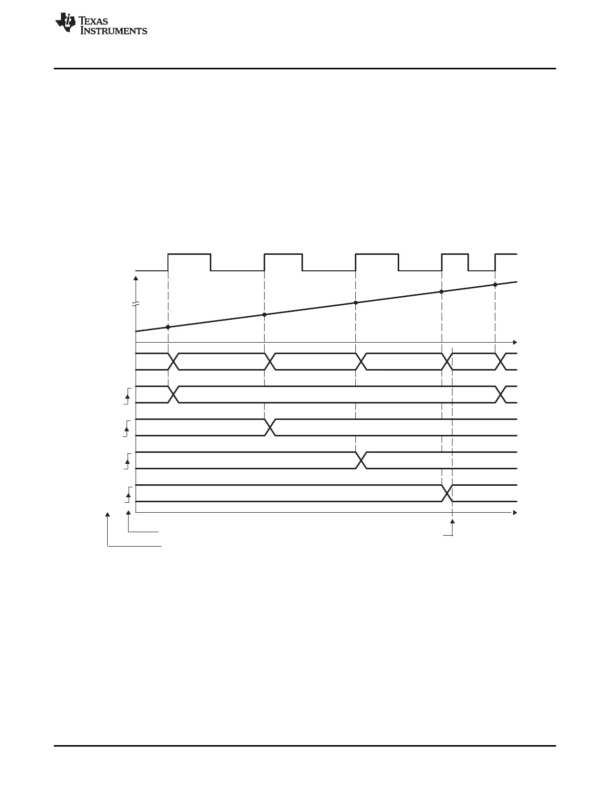
13.3.1 Absolute Time-Stamp Operation Rising Edge Trigger Example
Figure 13-10 shows an example of continuous capture operation (Mod4 counter wraps around). In this
figure, TSCTR counts-up without resetting and capture events are qualified on the rising edge only, this
gives period (and frequency) information.
On an event, the TSCTR contents (time-stamp) is first captured, then Mod4 counter is incremented to the
next state. When the TSCTR reaches FFFF FFFFh (maximum value), it wraps around to 0000 0000h (not
shown in Figure 13-10), if this occurs, the CTROVF (counter overflow) flag is set, and an interrupt (if
enabled) occurs, CTROVF (counter overflow) Flag is set, and an Interrupt (if enabled) occurs. Captured
time-stamps are valid at the point indicated by the diagram, after the 4th event, hence event CEVT4 can
conveniently be used to trigger an interrupt and the CPU can read data from the CAPn registers.
Figure 13-10. Capture Sequence for Absolute Time-Stamp, Rising Edge Detect