CEVT1
CEVT2
CEVT5
FFFFFFFF
CTR[0−31]
00000000
CAPx pin
t
MOD4
CTR
CAP1
CAP2
CAP3
CAP4
Capture registers [1−4]
CEVT3
CEVT4
0 1 2 3 0 1
XX
XX
t
2
XX
t
3
XX
t
4
CTR value at CEVT1
t
1
T
1
T
2
2 3 0
t
5
t
6
t
7
T
3
T
4
T
5
T
6
T
7
T
8
CEVT1
CEVT2
CEVT3
CEVT4
Polarity selection
www.ti.com
Applications
261
SPRUH91D–March 2013–Revised September 2016
Submit Documentation Feedback
Copyright © 2013–2016, Texas Instruments Incorporated
Enhanced Capture (eCAP) Module
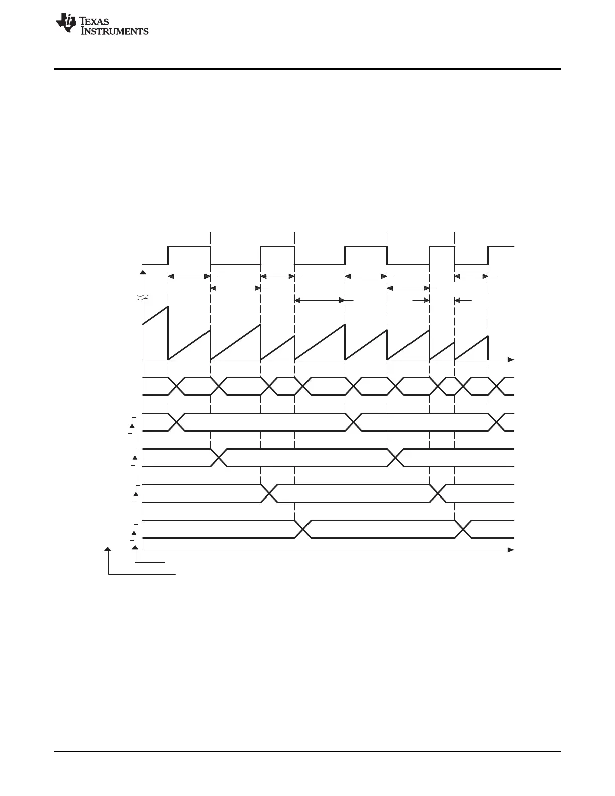
13.3.4 Time Difference (Delta) Operation Rising and Falling Edge Trigger Example
In Figure 13-13 the eCAP operating mode is almost the same as in previous section except Capture
events are qualified as either Rising or Falling edge, this now gives both Period and Duty cycle
information: Period1 = T
1
+ T
2
, Period2 = T
3
+ T
4
, …etc Duty Cycle1 (on-time %) = T
1
/ Period1 × 100%,
etc Duty Cycle1 (off-time %) = T
2
/ Period1 × 100%, etc
During initialization, you must write to the active registers for both period and compare. This will then
automatically copy the init values into the shadow values. For subsequent compare updates, that is,
during run-time, only the shadow registers must be used.
Figure 13-13. Capture Sequence for Delta Mode Time-Stamp, Rising and Falling Edge Detect