www.ti.com
Registers
979
SPRUH91D–March 2013–Revised September 2016
Submit Documentation Feedback
Copyright © 2013–2016, Texas Instruments Incorporated
Liquid Crystal Display Controller (LCDC)
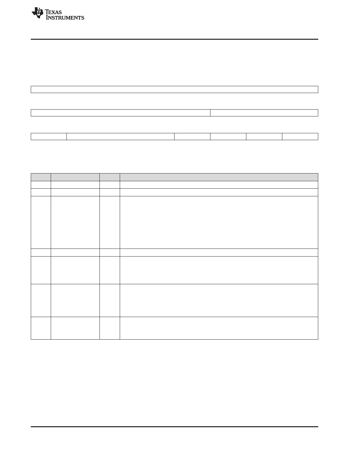
23.3.13 LCD DMA Control Register (LCDDMA_CTRL)
The LCD DMA control register (LCDDMA_CTRL) contains bits that control the LCD channel operation.
The LCDDMA_CTRL is shown in Figure 23-41 and described in Table 23-24.
Figure 23-41. LCD DMA Control Register (LCDDMA_CTRL)
31 16
Reserved
R-0
15 11 10 8
Reserved Reserved
R-0 R-0
7 6 4 3 2 1 0
Reserved BURST_SIZE Reserved EOF_INTEN BIGENDIAN FRAME_MODE
R-0 R/W-0 R-0 R/W-0 R/W-0 R/W-0
LEGEND: R/W = Read/Write; R = Read only; -n = value after reset
Table 23-24. LCD DMA Control Register (LCDDMA_CTRL) Field Descriptions
Bit Field Value Description
31-11 Reserved 0 Reserved
10-7 Reserved 0 Reserved
6-4 BURST_SIZE 0-7h Burst Size setting for DMA transfers (all DMA transfers are 32 bits wide)
0 Burst size of 1
1h Burst size of 2
2h Burst size of 4
3h Burst size of 8
4h Burst size of 16
5h-7h Reserved
3 Reserved 0 Reserved
2 EOF_INTEN End-of-Frame Interrupt Enable. Setting this bit allows the end-of-frame 0 or 1 status bits in the
LCD status register to trigger an interrupt.
0 End-of-frame 0/1 interrupt disabled
1 End-of-frame 0/1 interrupt enabled
1 BIGENDIAN Big Endian Enable. Use this bit when the processor is operating in Big Endian mode and writes
to the frame buffer(s) are less than 32 bits wide; in this scenario only, change the byte
alignment for data coming into the FIFO from the frame buffer(s).
0 Big Endian data reordering disabled
1 Big Endian data reordering enabled
0 FRAME_MODE Frame Mode
0 One frame buffer (FB0 only) used.
1 Two frame buffers used; DMA ping-pongs between FB0 and FB1 in this mode.