Architecture
www.ti.com
86
SPRUH91D–March 2013–Revised September 2016
Submit Documentation Feedback
Copyright © 2013–2016, Texas Instruments Incorporated
Memory Protection Unit (MPU)
5.2.3 Permission Structures
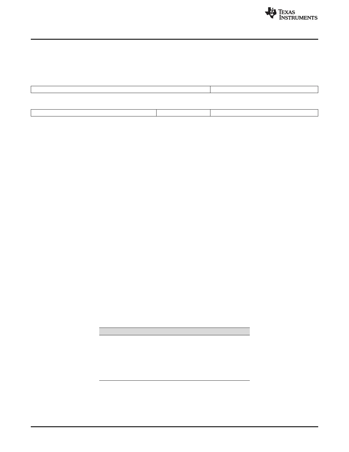
The MPU defines a per-range permission structure with three permission fields in a 32-bit permission
entry. Figure 5-2 shows the structure of a permission entry.
Figure 5-2. Permission Fields
31 22 21 20 19 18 17 16
Reserved Allowed IDs
AID11 AID10 AID9 AID8 AID7 AID6
15 14 13 12 11 10 9 8 6 5 4 3 2 1 0
Allowed IDs Reserved Access Types
AID5 AID4 AID3 AID2 AID1 AID0 AIX SR SW SX UR UW UX
5.2.3.1 Requestor-ID Based Access Controls
Each master on the device has an N-bit code associated with it that identifies it for privilege purposes.
This privilege ID accompanies all memory accesses made on behalf of that master. That is, when a
master triggers a memory access command, the privilege ID will be carried alongside the command.
Each memory protection range has an allowed ID (AID) field associated with it that indicates which
requestors may access the given address range. The MPU maps the privilege IDs of all the possible
requestors to bits in the allowed IDs field in the memory protection page attribute registers (MPPA).
• AID0 through AID11 are used to specify the allowed privilege IDs.
• An additional allowed ID bit, AIDX, captures access made by all privilege IDs not covered by AID0
through AID11.
When set to 1, the AID bit grants access to the corresponding ID. When cleared to 0, the AID bit denies
access to the corresponding requestor.
5.2.3.2 Request-Type Based Permissions
The memory protection model defines three fundamental functional access types: read, write, and
execute. Read and write refer to data accesses -- accesses originating via the load/store units on the CPU
or via a master peripheral. Execute refers to accesses associated with an instruction fetch.
The memory protection model allows controlling read, write, and execute permissions independently for
both user and supervisor mode. This results in six permission bits, listed in Table 5-4. For each bit, a 1
permits the access type and a 0 denies access. For example, UX = 1 means that User Mode may execute
from the given page. The memory protection unit allows you to specify all six of these bits separately; 64
different encodings are permitted altogether, although programs might not use all of them.
Table 5-4. Request Type Access Controls
Bit Field Description
5 SR Supervisor may read
4 SW Supervisor may write
3 SX Supervisor may execute
2 UR User may read
1 UW User may write
0 UX User may execute