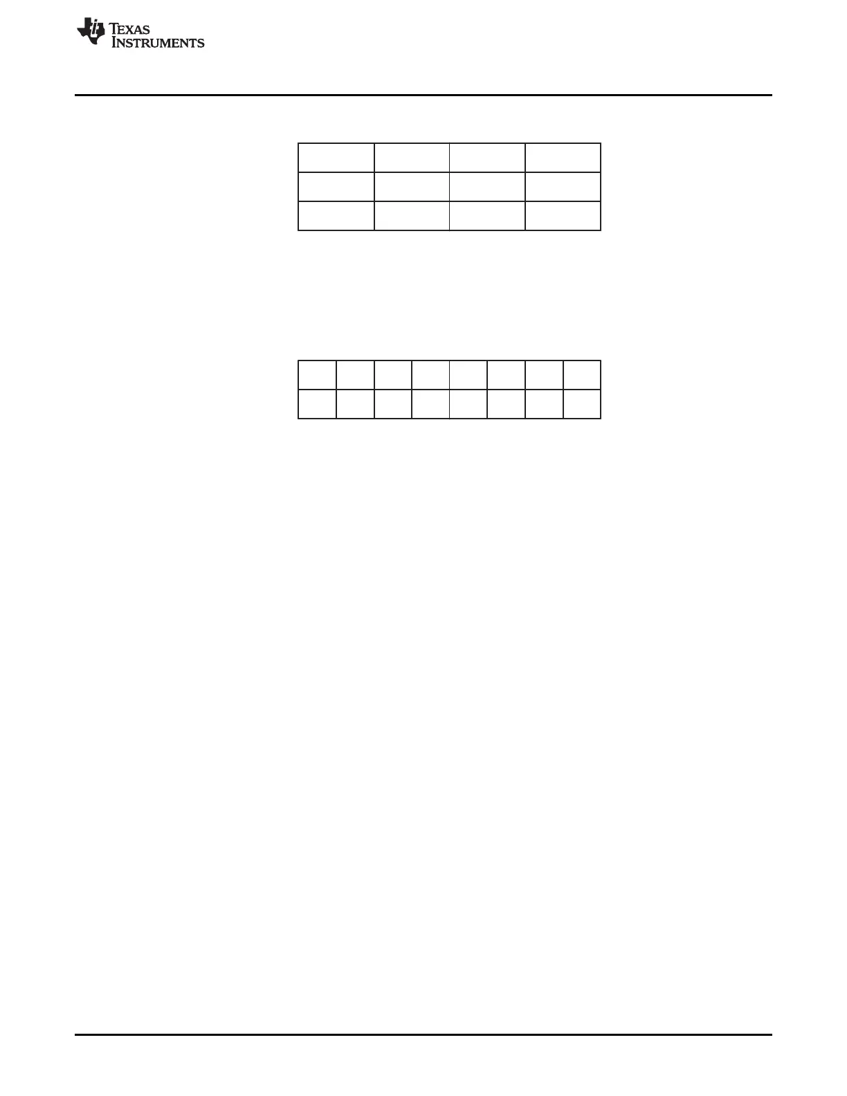
Base
P0
Bit
7
Base + 1
6 5 4 3 2 1 0
P1 P2 P3 P4 P5 P6 P7
P8 P9 P10 P11 P12 P13 P14 P15
Base
Pixel 0
Bit
7
Base + 1
Base + 2
6
Pixel 1
5 4
Pixel 2
3 2
Pixel 3
1 0
Pixel 4 Pixel 5 Pixel 6 Pixel 7
Pixel 8 Pixel 9 Pixel 10 Pixel 11
www.ti.com
Architecture
945
SPRUH91D–March 2013–Revised September 2016
Submit Documentation Feedback
Copyright © 2013–2016, Texas Instruments Incorporated
Liquid Crystal Display Controller (LCDC)
Figure 23-11. 2-BPP Data Memory Organization
Figure 23-12. 1-BPP Data Memory Organization
23.2.5.3 Palette
As explained in the previous section, the pixel data is an index of palette entry (when palette is used). The
number of colors supported is given by 2
number of BPP
. However, due to a limitation of the gray-
scaler/serializer block, fewer grayscales or colors may be supported.
The PLM field (in RASTER_CTRL) affects the palette loading:
• If PLM is 00b (palette-plus-data mode) or 01b (palette-only mode), the palette is loaded by the DMA
engine at the very beginning, which is followed by the loading of pixel data.
• If PLM is 10b (data-only mode), the palette is not loaded. Instead, the DMA engine loads the pixel data
immediately.
23.2.5.4 Gray-Scaler/Serializer
23.2.5.4.1 Passive (STN) Mode
Once a palette entry is selected from the look-up palette by the pixel data, its content is sent to the gray-
scaler/serializer. If it is monochrome data, it is encoded as 4 bits. If it is color data, it is encoded as 4 bits
(Red), 4 bits (Green), and 4 bits (Blue).
These 4-bit values are used to select one of the 16 intensity levels, as shown in Table 23-7. A patented
algorithm is used during this processing to provide an optimized intensity value that matches the eye's
visual perception of color/gray gradations.
23.2.5.4.2 Active (TFT) Mode
The gray-scaler/serializer is bypassed.