EMA_CS[n]
EMA_WE
EMA_OE
EMA_WAIT
EMA_BA[1:0]
EMA_D[x:0]
EMA_WE_DQM[x:0]
EMA_A[x:0]
EMIFA
Architecture
www.ti.com
710
SPRUH91D–March 2013–Revised September 2016
Submit Documentation Feedback
Copyright © 2013–2016, Texas Instruments Incorporated
External Memory Interface A (EMIFA)
18.2.5 Asynchronous Controller and Interface
The EMIFA easily interfaces to a variety of asynchronous devices including NOR Flash, NAND Flash, and
SRAM. It can be operated in two major modes (see Table 18-14):
• Normal Mode
• Select Strobe Mode
Table 18-14. Normal Mode vs. Select Strobe Mode
Mode Function of EMA_WE_DQM pins Operation of EMA_CS[5:2]
Normal Mode Byte enables Active during the entire asynchronous access cycle
Select Strobe Mode Byte enables Active only during the strobe period of an access cycle
The first mode of operation is Normal Mode, in which the EMA_WE_DQM pins of the EMIFA function as
byte enables. In this mode, the EMA_CS[5:2] pins behaves as typical chip select signals, remaining active
for the duration of the asynchronous access. See Section 18.2.5.1 for an example interface with multiple
8-bit devices.
The second mode of operation is Select Strobe Mode, in which the EMA_CS[5:2] pins act as a strobe,
active only during the strobe period of an access. In this mode, the EMA_WE_DQM pins of the EMIFA
function as standard byte enables for reads and writes. A summary of the differences between the two
modes of operation are shown in Table 18-14. Refer to Section 18.2.5.4 for the details of asynchronous
operations in Normal Mode, and to Section 18.2.5.5 for the details of asynchronous operations in Select
Strobe Mode. The EMIFA hardware defaults to Normal Mode, but can be manually switched to Select
Strobe Mode by setting the SS bit in the asynchronous m (m = 1, 2, 3, or 4) configuration register
(CEnCFG) (n = 2, 3, 4, or 5). Throughout the chapter, m can hold the values 1, 2, 3 or 4; and n can hold
the values 2, 3, 4, or 5.
In both Normal Mode and Select Strobe Mode, the EMIFA can be configured to operate in a sub-mode
called NAND Flash Mode. In NAND Flash Mode, the EMIFA is able to calculate an error correction code
(ECC) for transfers up to 518 bytes.
The EMIFA also provides configurable cycle timing parameters and an Extended Wait Mode that allows
the connected device to extend the strobe period of an access cycle. The following sections describe the
features related to interfacing with external asynchronous devices.
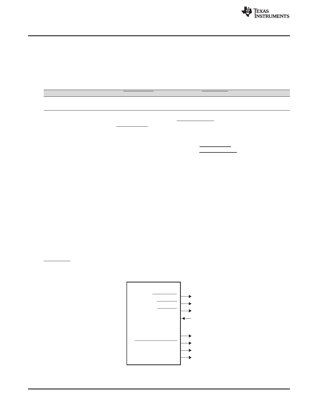
18.2.5.1 Interfacing to Asynchronous Memory
Figure 18-7 shows the EMIFA's external pins used in interfacing with an asynchronous device. In
EMA_CS[n], n = 2, 3, 4, or 5.
Figure 18-7. EMIFA Asynchronous Interface