Counter (”timer”)
SyncIn
32
CAP1 reg
CAP2 reg
CAP4 reg
CAP3 reg
Interrupt I/FECAPxINT
Sequencing
Edge detection
Edge polarity
Prescale
ECAPx
pin
Note:
Same pin
depends on
operating
mode
Counter (”timer”)
SyncIn
32
Capture
mode
APWM
mode
Period reg
(active) (”CAP1”)
Compare reg
(active) (”CAP2”)
Period reg
(shadow) (”CAP3”)
(shadow) (”CAP4”)
Compare reg
Interrupt I/FECAPxINT
PWM
Compare logic
APWMx
pin
Or
Syncout
Architecture
www.ti.com
246
SPRUH91D–March 2013–Revised September 2016
Submit Documentation Feedback
Copyright © 2013–2016, Texas Instruments Incorporated
Enhanced Capture (eCAP) Module
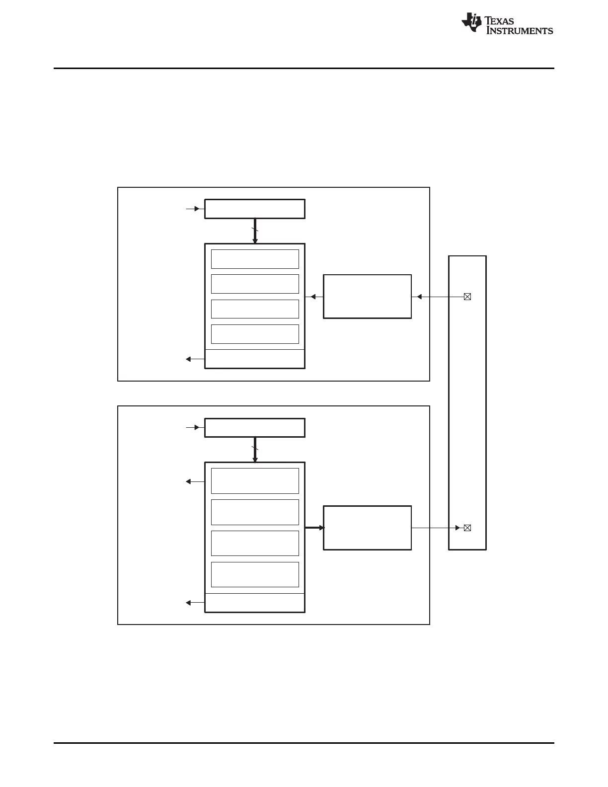
13.2.1 Capture and APWM Operating Mode
You can use the eCAP module resources to implement a single-channel PWM generator (with 32 bit
capabilities) when it is not being used for input captures. The counter operates in count-up mode,
providing a time-base for asymmetrical pulse width modulation (PWM) waveforms. The CAP1 and CAP2
registers become the active period and compare registers, respectively, while CAP3 and CAP4 registers
become the period and capture shadow registers, respectively. Figure 13-2 is a high-level view of both the
capture and auxiliary pulse-width modulator (APWM) modes of operation.
Figure 13-2. Capture and APWM Modes of Operation
(1) A single pin is shared between CAP and APWM functions. In capture mode, it is an input; in APWM mode, it
is an output.
(2) In APWM mode, writing any value to CAP1/CAP2 active registers also writes the same value to the
corresponding shadow registers CAP3/CAP4. This emulates immediate mode. Writing to the shadow
registers CAP3/CAP4 invokes the shadow mode.

 Loading...


