PSC Registers
www.ti.com
162
SPRUH91D–March 2013–Revised September 2016
Submit Documentation Feedback
Copyright © 2013–2016, Texas Instruments Incorporated
Power and Sleep Controller (PSC)
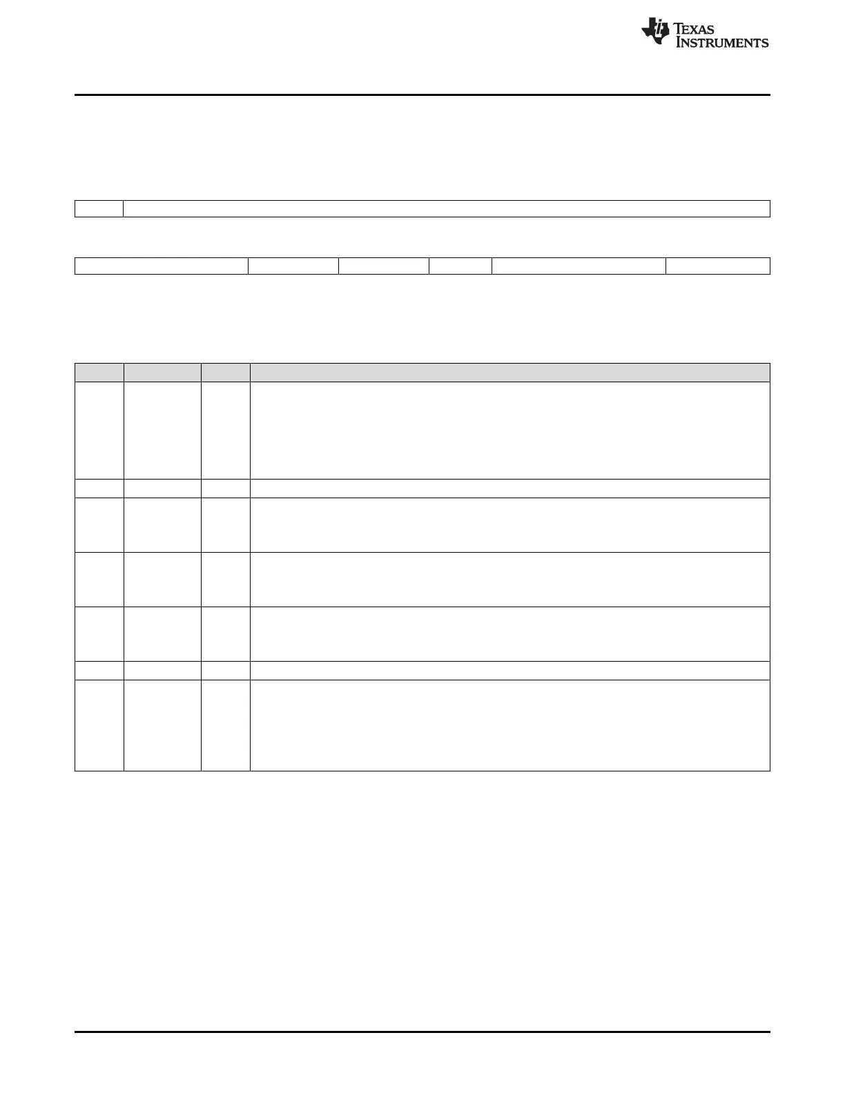
8.6.18 PSC0 Module Control n Register (modules 0-15) (MDCTLn)
The PSC0 module control n register (MDCTLn) is shown in Figure 8-18 and described in Table 8-23.
Figure 8-18. PSC0 Module Control n Register (MDCTLn)
31 30 16
FORCE Reserved
R/W-0 R-0
15 11 10 9 8 7 3 2 0
Reserved EMUIHBIE EMURSTIE LRST Reserved NEXT
R-0 R/W-0 R/W-0 R/W-0 R-0 R/W-0
LEGEND: R/W = Read/Write; R = Read only; -n = value after reset
Table 8-23. PSC0 Module Control n Register (MDCTLn) Field Descriptions
Bit Field Value Description
31 FORCE Force enable. This bit forces the module state programmed in the NEXT bit in the module control 15
register (MDCTL15), ignoring and bypassing all the clock stop request handshakes managed by the
PSC to change the state of the clocks to the module.
Note: It is not recommended to use the FORCE bit to disable the module clock, unless specified.
0 Force is disabled.
1 Force is enabled.
30-11 Reserved 0 Reserved
10 EMUIHBIE Interrupt enable for emulation alters module state. This bit applies to DSP module (module 15).
0 Disable interrupt.
1 Enable interrupt.
9 EMURSTIE Interrupt enable for emulation alters reset. This bit applies to DSP module (module 15).
0 Disable interrupt.
1 Enable interrupt.
8 LRST Module local reset control. This bit applies to DSP module (module 15).
0 Assert local reset
1 De-assert local reset
7-3 Reserved 0 Reserved
2-0 NEXT 0-3h Module next state.
0 SwRstDisable state
1h SyncReset state
2h Disable state
3h Enable state