Parameter set 0
Parameter set 1
Parameter set 3
Parameter set 2
Parameter set n−1
Parameter set n−2
Set
#
0
1
2
3
n−2
n−1
DSTBIDX
BCNTRLD
Rsvd
DSTCIDX
CCNT
SRCCIDX
LINK
SRCBIDX
DST
BCNT ACNT
SRC
OPT
PaRAM PaRAM set
+0h
+4h
+8h
+Ch
Byte
address
+1Ch
+18h
+14h
+10h
offset
Parameter set nn
www.ti.com
Architecture
447
SPRUH91D–March 2013–Revised September 2016
Submit Documentation Feedback
Copyright © 2013–2016, Texas Instruments Incorporated
Enhanced Direct Memory Access (EDMA3) Controller
16.2.3 Parameter RAM (PaRAM)
The EDMA3 controller is a RAM-based architecture. The transfer context (source/destination addresses,
count, indexes, etc.) for DMA or QDMA channels is programmed in a parameter RAM table within the
EDMA3CC, referred to as PaRAM. The PaRAM table is segmented into multiple PaRAM sets. Each
PaRAM set includes eight 4-byte PaRAM set entries (32-bytes total per PaRAM set), which includes
typical DMA transfer parameters such as source address, destination address, transfer counts, indexes,
options, etc. See your device-specific data manual for the addresses of the PaRAM set entries.
The PaRAM structure supports flexible ping-pong, circular buffering, channel chaining, and autoreloading
(linking). The first n PaRAM sets are directly mapped to the DMA channels (where n is the number of
DMA channels supported in the EDMA3CC for a specific device). The remaining PaRAM sets can be used
for link entries or associated with QDMA channels. Additionally if the DMA channels are not used, the
PaRAM sets associated with the unused DMA channels can also be used for link entries or QDMA
channels.
NOTE: By default, QDMA channels are mapped to PaRAM set 0. These should be remapped before
use, see Section 16.2.6.2.
16.2.3.1 PaRAM Set
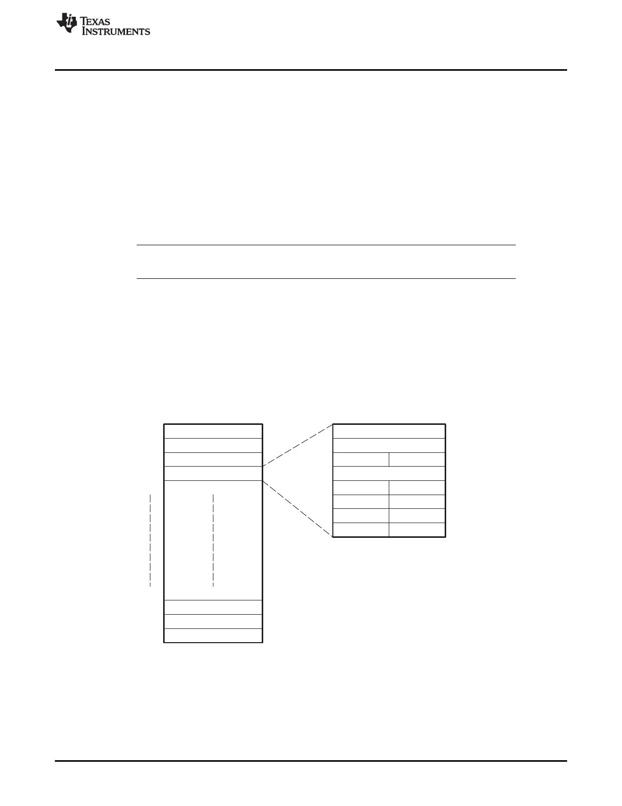
Each parameter set of PaRAM is organized into eight 32-bit words or 32 bytes, as shown in Figure 16-7
and described in Table 16-1. Each PaRAM set consists of 16-bit and 32-bit parameters.
Figure 16-7. PaRAM Set
Note: n is the number of PaRAM sets supported in the EDMA3CC for a specific device.