EMIFB
Memory
Controller
Registers
State
Machine
CHIP_RST
MOD_G_RST
EMIFB
PSC
HardReset
fromPLL
Architecture
www.ti.com
802
SPRUH91D–March 2013–Revised September 2016
Submit Documentation Feedback
Copyright © 2013–2016, Texas Instruments Incorporated
External Memory Interface B (EMIFB)
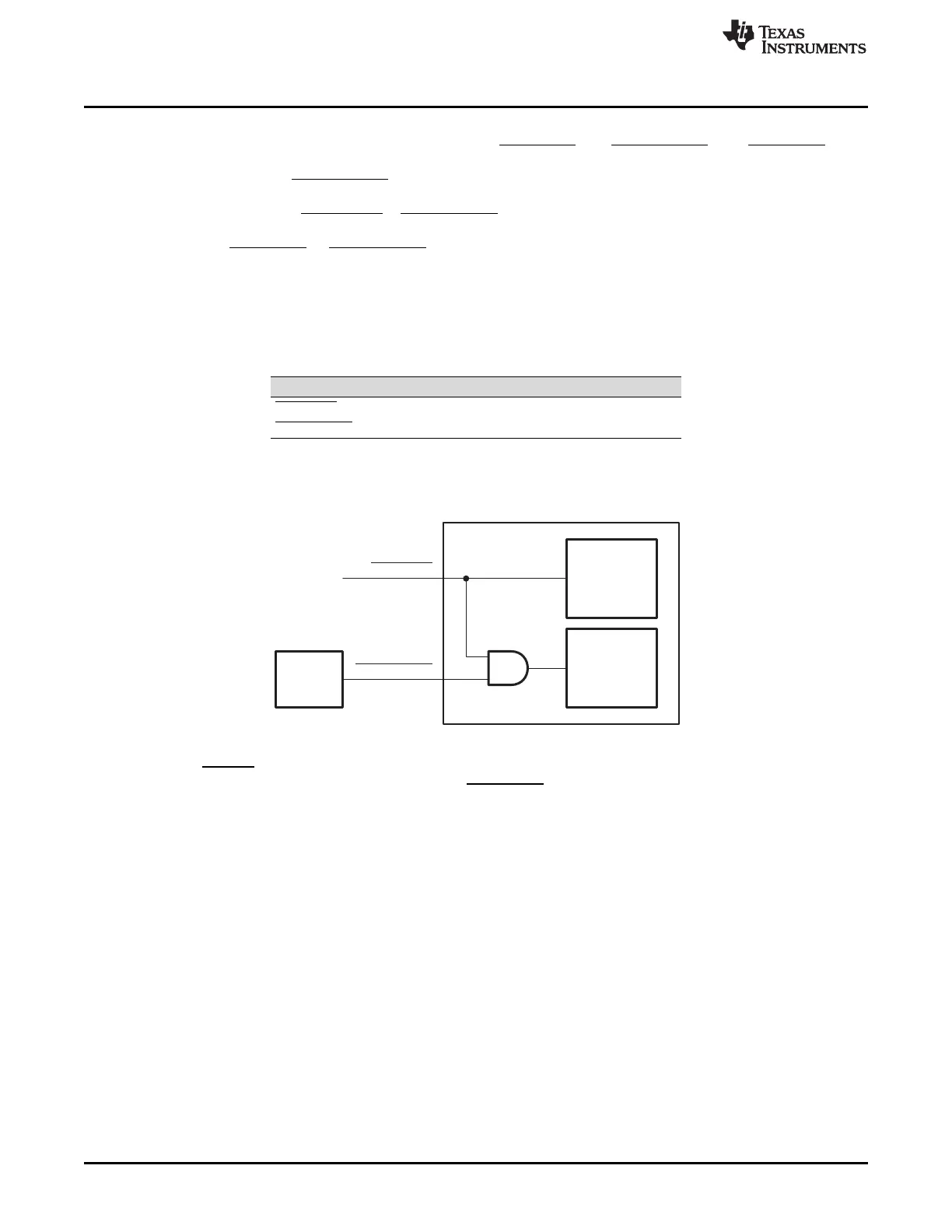
19.2.7 Reset and Initialization Considerations
The EMIFB memory controller has two reset signals, CHIP_RST and MOD_G_RST. The CHIP_RST is a
module-level reset that resets both the state machine as well as the EMIFB memory controller memory-
mapped registers. The MOD_G_RST resets the state machine only. If the EMIFB memory controller is
reset independently of other peripherals, the user's software should not perform memory, as well as
register accesses, while CHIP_RST or MOD_G_RST are asserted. If memory or register accesses are
performed while the EMIFB memory controller is in the reset state, other masters may hang. Following the
rising edge of CHIP_RST or MOD_G_RST, the EMIFB memory controller immediately begins its
initialization sequence. Command and data stored in the EMIFB memory controller FIFOs are lost.
Table 19-18 describes the different methods for asserting each reset signal. The Power and Sleep
Controller (PSC) acts as a master controller for power management for all of the peripherals on the
device. Figure 19-9 shows the EMIFB memory controller reset diagram.
Table 19-18. Reset Sources
Reset Signal Reset Source
CHIP_RST Hardware/device reset
MOD_G_RST Power and sleep controller
Figure 19-9. EMIFB Memory Controller Reset Block Diagram
When the RESET pin on the device is asserted or a system reset is issued from Code Composer Studio,
EMIFB memory controller's behavior is same as CHIP_RST assertion. In all these cases, the EMIFB will
exit the reset state when the reset is released and after the PLL controller releases the entire device from
reset. In all cases, EMIFB automatically begins running the SDRAM initialization sequence after coming
out of reset. Even though the initialization procedure is automatic, a special procedure, found in
Section 19.2.6.5 must still be followed.
19.2.8 Interrupt Support
EMIFB supports Line Trap Interrupt, which is caused by use of unsupported addressing mode. EMIFB
supports only linear incrementing and cache line wrap addressing modes . If an access request for an
unsupported addressing mode is received, the EMIFB will set the LT bit in the interrupt raw register (IRR)
and treat the request as a linear incrementing request. For details on EMIFB interrupt multiplexing, see
your device-specific data manual. For details on interrupt support and interrupt events, see the DSP
Subsystem chapter chapter.
EDMA Event Support
EMIFB memory controller is a DMA slave peripheral and therefore does not generate DMA events. Data
read and write requests may be made directly, by masters and the DMA.