www.ti.com
Registers
537
SPRUH91D–March 2013–Revised September 2016
Submit Documentation Feedback
Copyright © 2013–2016, Texas Instruments Incorporated
Enhanced Direct Memory Access (EDMA3) Controller
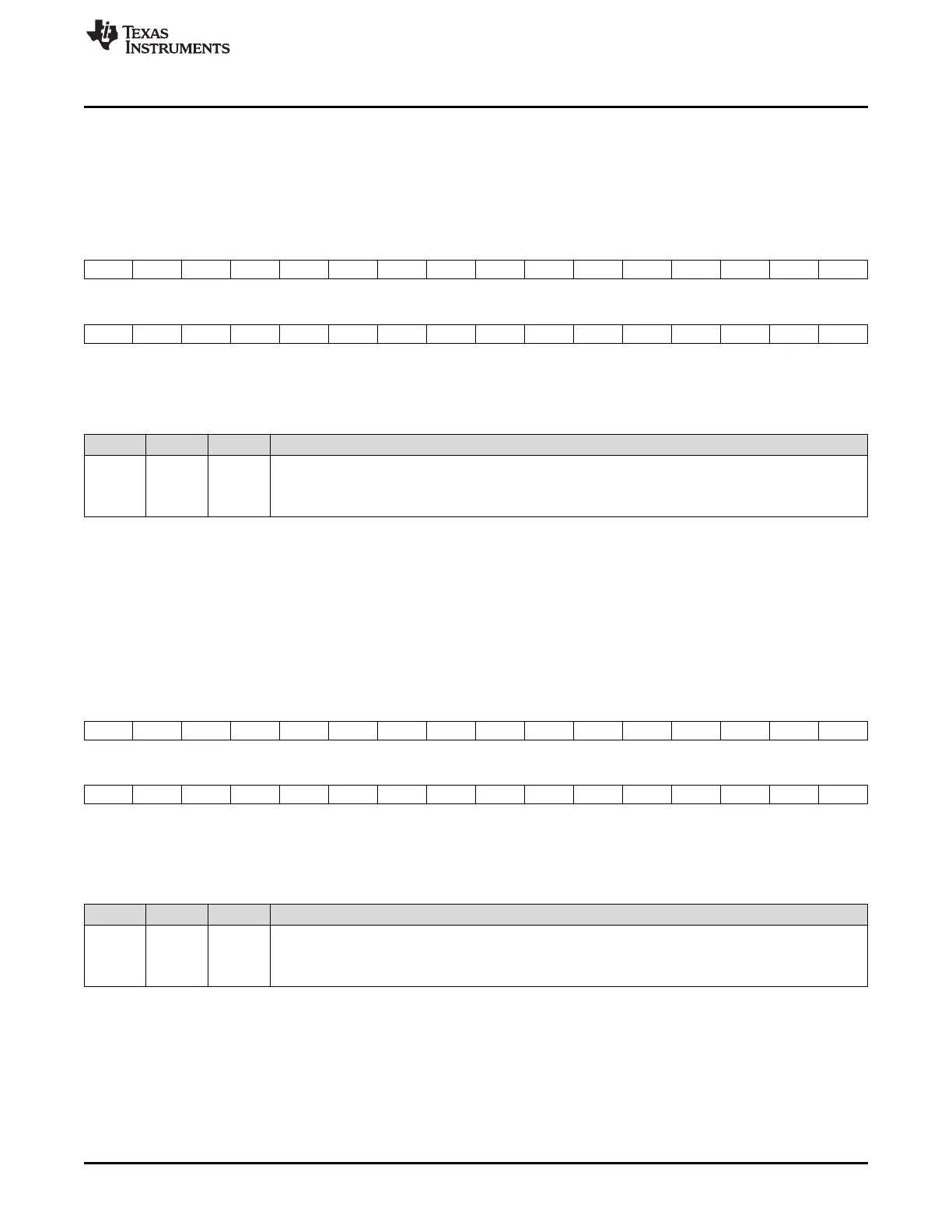
16.4.2.6.2 Interrupt Enable Clear Register (IECR)
The interrupt enable clear register (IECR) is used to clear interrupts. Writes of 1 to the bits in IECR clear
the corresponding interrupt bits in the interrupt enable registers (IER); writes of 0 have no effect.
The IECR is shown in Figure 16-71 and described in Table 16-50.
Figure 16-71. Interrupt Enable Clear Register (IECR)
31 30 29 28 27 26 25 24 23 22 21 20 19 18 17 16
I31 I30 I29 I28 I27 I26 I25 I24 I23 I22 I21 I20 I19 I18 I17 16
W-0 W-0 W-0 W-0 W-0 W-0 W-0 W-0 W-0 W-0 W-0 W-0 W-0 W-0 W-0 W-0
15 14 13 12 11 10 9 8 7 6 5 4 3 2 1 0
I15 I14 I13 I12 I11 I10 I9 I8 I7 I6 I5 I4 I3 I2 I1 I0
W-0 W-0 W-0 W-0 W-0 W-0 W-0 W-0 W-0 W-0 W-0 W-0 W-0 W-0 W-0 W-0
LEGEND: W = Write only; -n = value after reset
Table 16-50. Interrupt Enable Clear Register (IECR) Field Descriptions
Bit Field Value Description
31-0 En Interrupt enable clear for channels 0-31.
0 No effect
1 Corresponding bit in the interrupt enable register (IER) is cleared (In = 0).
16.4.2.6.3 Interrupt Enable Set Register (IESR)
The interrupt enable set register (IESR) is used to enable interrupts. Writes of 1 to the bits in IESR set the
corresponding interrupt bits in the interrupt enable registers (IER); writes of 0 have no effect.
The IESR is shown in Figure 16-72 and described in Table 16-51.
Figure 16-72. Interrupt Enable Set Register (IESR)
31 30 29 28 27 26 25 24 23 22 21 20 19 18 17 16
I31 I30 I29 I28 I27 I26 I25 I24 I23 I22 I21 I20 I19 II8 I17 I16
W-0 W-0 W-0 W-0 W-0 W-0 W-0 W-0 W-0 W-0 W-0 W-0 W-0 W-0 W-0 W-0
15 14 13 12 11 10 9 8 7 6 5 4 3 2 1 0
I15 I14 I13 I12 I11 I10 I9 I8 I7 I6 I5 I4 I3 I2 I1 I0
W-0 W-0 W-0 W-0 W-0 W-0 W-0 W-0 W-0 W-0 W-0 W-0 W-0 W-0 W-0 W-0
LEGEND: W = Write only; -n = value after reset
Table 16-51. Interrupt Enable Set Register (IESR) Field Descriptions
Bit Field Value Description
31-0 En Interrupt enable set for channels 0-31.
0 No effect.
1 Corresponding bit in the interrupt enable register (IER) is set (In = 1).

 Loading...


