R_HOLD w
ǒ
t
H
* t
OH
(m)
Ǔ
t
cyc
* 1
R_SETUP ) R_STROBE ) R_HOLD w
t
RC
(m)
t
cyc
* 3
R_SETUP + R_STROBE ≥
t
ACC
(m) t
SU
t
cyc
- 2
+
www.ti.com
Example Configuration
741
SPRUH91D–March 2013–Revised September 2016
Submit Documentation Feedback
Copyright © 2013–2016, Texas Instruments Incorporated
External Memory Interface A (EMIFA)
18.3.2.2 Interfacing to Asynchronous SRAM (ASRAM)
The following example describes how to interface the EMIFA to the Toshiba TC55V16100FT-12 device.
18.3.2.2.1 Meeting AC Timing Requirements for ASRAM
When configuring the EMIFA to interface to ASRAM, you must consider the AC timing requirements of the
ASRAM as well as the AC timing requirements of the EMIFA. These can be found in the data sheet for
each respective device. The read and write asynchronous cycles are programmed separately in the
asynchronous configuration register (CEnCFG).
For a read access, Table 18-31 to Table 18-33 list the AC timing specifications that must be considered.
Table 18-31. EMIFA Input Timing Requirements
Parameter Description
t
SU
Data Setup time, data valid before EMA_OE high
t
H
Data Hold time, data valid after EMA_OE high
Table 18-32. ASRAM Output Timing Characteristics
Parameter Description
t
ACC
Address Access time
t
OH
Output data Hold time for address change
t
COD
Output Disable time from chip enable
Table 18-33. ASRAM Input Timing Requirement for a Read
Parameter Description
t
RC
Read Cycle time
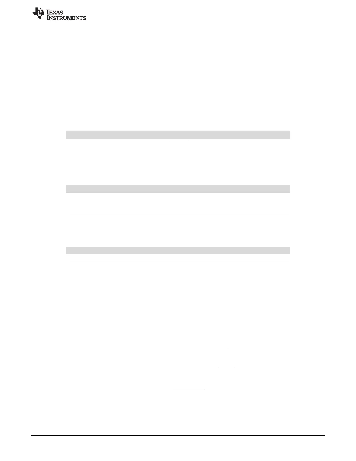
Figure 18-23 shows an asynchronous read access and describes how the EMIFA and ASRAM AC timing
requirements work together to define the values for R_SETUP, R_STROBE, and R_HOLD.
From Figure 18-23, the following equations may be derived. t
cyc
is the period at which the EMIFA operates.
The R_SETUP, R_STROBE, and R_HOLD fields are programmed in terms of EMIFA cycles where as the
data sheet specifications are typically given in nanoseconds. This explains the presence of t
cyc
in the
denominator of the following equations. A minus 1 is included in the equations because each field in
CEnCFG is programmed in terms of EMIFA clock cycles, minus 1 cycle. For example, R_SETUP is equal
to R_SETUP width in EMIFA clock cycles minus 1 cycle.