Architecture
www.ti.com
334
SPRUH91D–March 2013–Revised September 2016
Submit Documentation Feedback
Copyright © 2013–2016, Texas Instruments Incorporated
Enhanced High-Resolution Pulse-Width Modulator (eHRPWM)
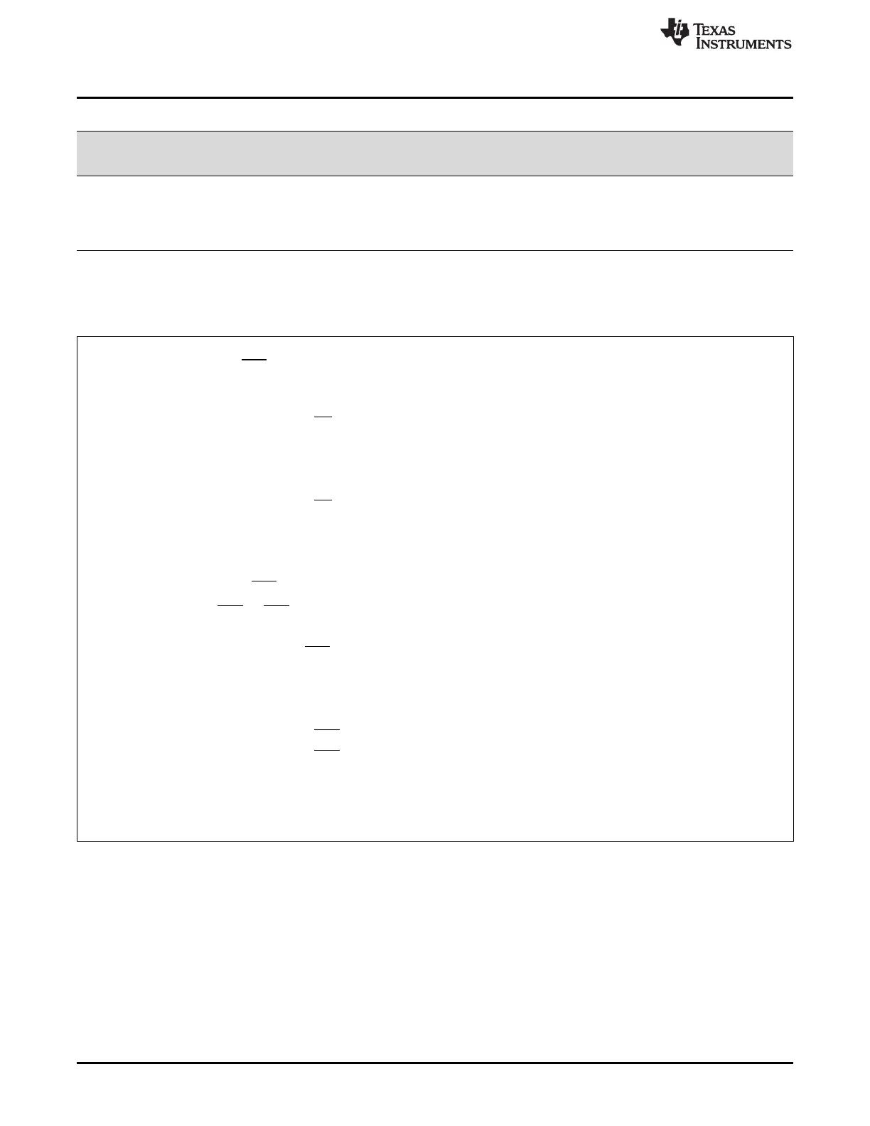
Table 14-29. Possible Actions On a Trip Event
TZCTL[TZA]
and/or
TZCTL[TZB]
EPWMxA
and/or
EPWMxB Comment
0 High-Impedance Tripped
1h Force to High State Tripped
2h Force to Low State Tripped
3h No Change Do Nothing. No change is made to the output.
Example 14-2. Trip-Zone Configurations
Scenario A:
A one-shot trip event on TZ1 pulls both EPWM1A, EPWM1B low and also forces EPWM2A and EPWM2B
high.
• Configure the ePWM1 registers as follows:
– TZSEL[OSHT1] = 1: enables TZ as a one-shot event source for ePWM1
– TZCTL[TZA] = 2: EPWM1A will be forced low on a trip event.
– TZCTL[TZB] = 2: EPWM1B will be forced low on a trip event.
• Configure the ePWM2 registers as follows:
– TZSEL[OSHT1] = 1: enables TZ as a one-shot event source for ePWM2
– TZCTL[TZA] = 1: EPWM2A will be forced high on a trip event.
– TZCTL[TZB] = 1: EPWM2B will be forced high on a trip event.
Scenario B:
A cycle-by-cycle event on TZ5 pulls both EPWM1A, EPWM1B low.
A one-shot event on TZ1 or TZ6 puts EPWM2A into a high impedance state.
• Configure the ePWM1 registers as follows:
– TZSEL[CBC5] = 1: enables TZ5 as a one-shot event source for ePWM1
– TZCTL[TZA] = 2: EPWM1A will be forced low on a trip event.
– TZCTL[TZB] = 2: EPWM1B will be forced low on a trip event.
• Configure the ePWM2 registers as follows:
– TZSEL[OSHT1] = 1: enables TZ1 as a one-shot event source for ePWM2
– TZSEL[OSHT6] = 1: enables TZ6 as a one-shot event source for ePWM1
– TZCTL[TZA] = 0: EPWM1A will be put into a high-impedance state on a trip event.
– TZCTL[TZB] = 3: EPWM1B will ignore the trip event.
14.2.8.4 Generating Trip Event Interrupts
Figure 14-37 and Figure 14-38 illustrate the trip-zone submodule control and interrupt logic, respectively.