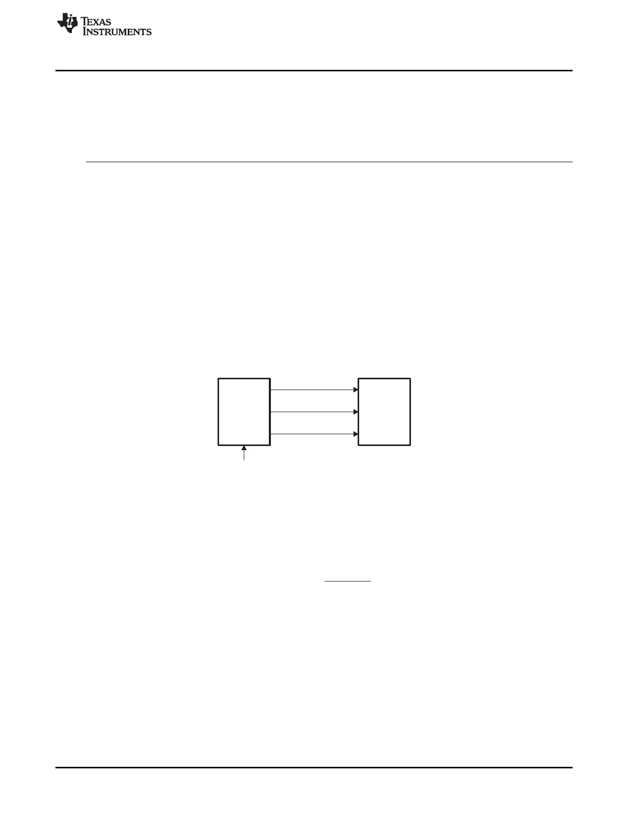
PixelClockDerived
fromLCD_CLK
HSYNC/LineClock
VSYNC/FrameClock
LCD
Controller
Display
LCD_CLK
www.ti.com
Introduction
933
SPRUH91D–March 2013–Revised September 2016
Submit Documentation Feedback
Copyright © 2013–2016, Texas Instruments Incorporated
Liquid Crystal Display Controller (LCDC)
23.1.2 Features
See your device-specific data manual to check the features supported by the LCD controller.
23.1.3 Terminology
Term Meaning
Passive (STN) device Refers to the Super-Twisted Nematic (STN) display device.
Active (TFT) device Refers to the Thin-Film Transistor (TFT) display device.
BPP Bits per pixel; that is, the number of bits used for each pixel. In some
documentation, this is also referred to as color depth.
RGB Red, Green, Blue
23.2 Architecture
23.2.1 Clocking
This section details the various clocks and signals. Figure 23-2 shows input and output LCD controller
clocks.
Figure 23-2. Input and Output Clocks
23.2.1.1 Pixel Clock
The pixel clock (LCD_PCLK) frequency is derived from LCD_CLK, the reference clock to this LCD module
(see Figure 23-2). The pixel clock is used by the LCD display to clock the pixel data into the line shift
register.
where CLKDIV is a field in the LCD_CTRL register and should not be 0 or 1.
• Passive (STN) mode. LCD_PCLK only transitions when valid data is available for output. It does not
transition when the horizontal clock is asserted or during wait state insertion.
• Active (TFT) mode. LCD_PCLK continuously toggles as long as the Raster Controller is enabled.
 Loading...


