CA CA CA
CA
CB CB
CB
CB
TBCNT
EPWMxA
EPWMxB
TBPRD
(value)
Architecture
www.ti.com
320
SPRUH91D–March 2013–Revised September 2016
Submit Documentation Feedback
Copyright © 2013–2016, Texas Instruments Incorporated
Enhanced High-Resolution Pulse-Width Modulator (eHRPWM)
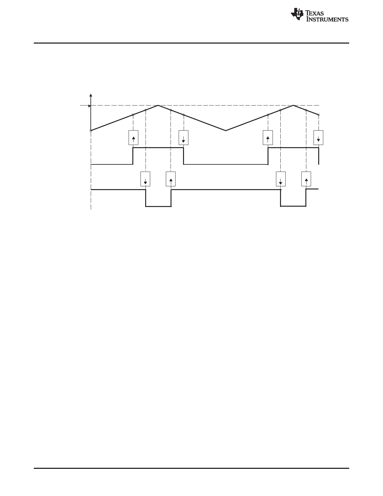
Table 14-21 and Table 14-22 contains initialization and runtime register configurations for the waveforms
in Figure 14-26. Use the code in Example 14-1 to define the headers.
Figure 14-26. Up-Down-Count, Dual Edge Symmetric Waveform, With Independent Modulation on
EPWMxA and EPWMxB — Complementary
(1) PWM period = 2 × TBPRD × T
TBCLK
(2) Duty modulation for EPWMxA is set by CMPA, and is active low, i.e., low time duty proportional to CMPA
(3) Duty modulation for EPWMxB is set by CMPB and is active high, i.e., high time duty proportional to CMPB
(4) Outputs EPWMx can drive upper/lower (complementary) power switches
(5) Dead-band = CMPB - CMPA (fully programmable edge placement by software). Note the dead-band module
is also available if the more classical edge delay method is required.