Clock and
reset logic
Receive
DMA engine
Interrupt
controller
Transmit
DMA engine
Control
registers
Configuration bus
EMAC
control
module
Configuration bus
RAM
State
FIFO
Receive
FIFO
Transmit MAC
transmitter
Statistics
receiver
MAC
SYNC
MII
address
Receive
RMII
Architecture
www.ti.com
596
SPRUH91D–March 2013–Revised September 2016
Submit Documentation Feedback
Copyright © 2013–2016, Texas Instruments Incorporated
EMAC/MDIO Module
17.2.8 EMAC Module
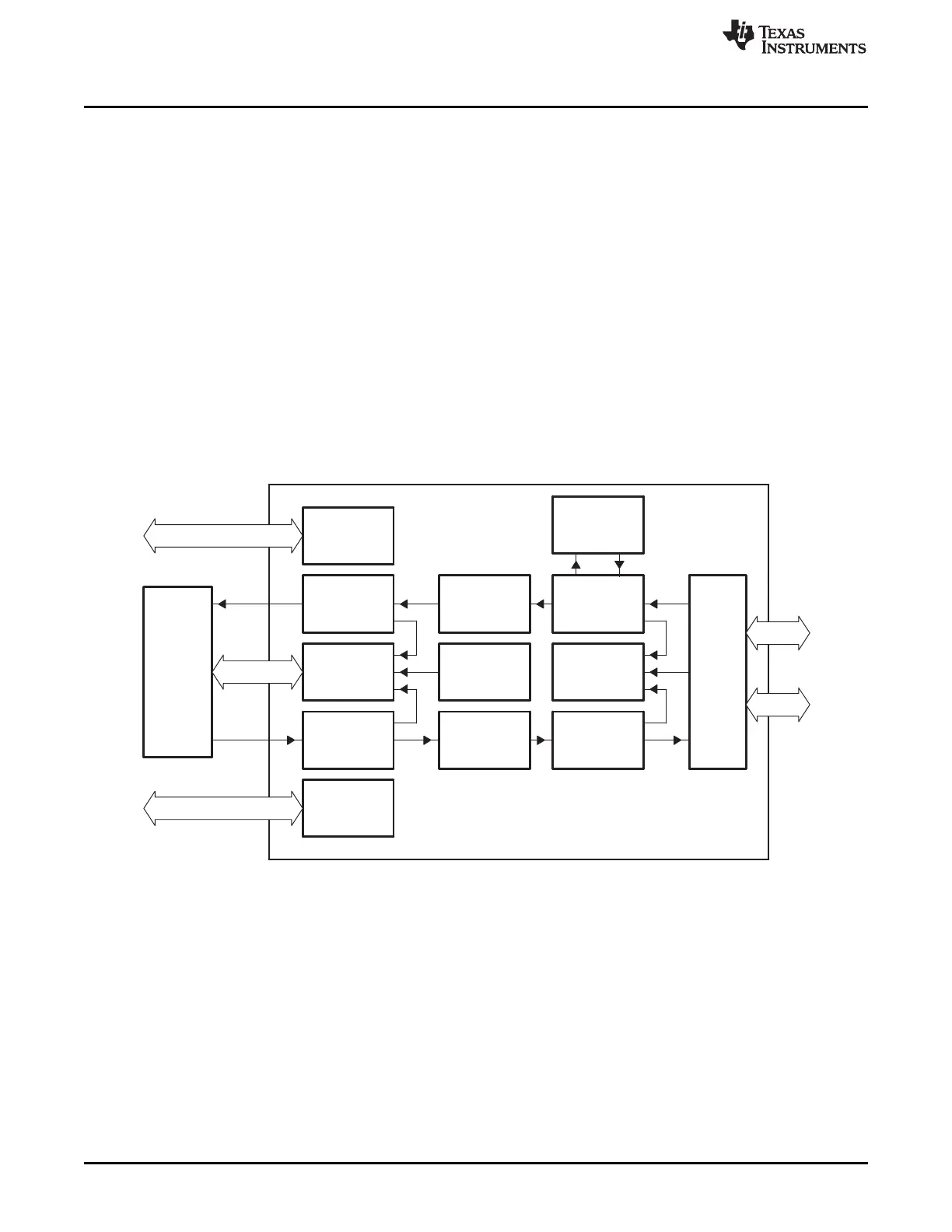
This section discusses the architecture and basic function of the EMAC module.
17.2.8.1 EMAC Module Components
The EMAC module (Figure 17-11) interfaces to the outside world through the Media Independent Interface
(MII) and/or Reduced Media Independent Interface (RMII). The interface between the EMAC module and
the system core is provided through the EMAC control module. The EMAC consists of the following logical
components:
• The receive path includes: receive DMA engine, receive FIFO, and MAC receiver
• The transmit path includes: transmit DMA engine, transmit FIFO, and MAC transmitter
• Statistics logic
• State RAM
• Interrupt controller
• Control registers and logic
• Clock and reset logic
Figure 17-11. EMAC Module Block Diagram
17.2.8.1.1 Receive DMA Engine
The receive DMA engine is the interface between the receive FIFO and the system core. It interfaces to
the CPU through the bus arbiter in the EMAC control module. This DMA engine is totally independent of
the device DMA.
17.2.8.1.2 Receive FIFO
The receive FIFO consists of three cells of 64-bytes each and associated control logic. The FIFO buffers
receive data in preparation for writing into packet buffers in device memory.